BOATBUILDING WITH A DIFFERENCE
VIII
(For Aspiring Amateurs)
By Barend
Migchelsen
(Click
here for Barend's book page)
A Laser-type Car Topper
In Montreal, the yearly Boat Show
is held early in the year.
Notwithstanding knowing better,
every year I still go there with the (very vague) hope of seeing
something with more character than the usual assortment of plastic
toys and aluminum cans. And always, without fail, there is some
fiberglass contraption that is hailed as “the boat of the
year”, a “breakthrough”, or whatever nice superlative
they can think of.
Usually, there is not much new
to it, and you never hear or see more of it after the show.
Over all these years, I have seen
only three exceptions that survived their 15-minutes-of-being-famous.
They are here to stay. The three boats are: the Optimist Pram
which has proven itself as an excellent sail-trainer, the Hobie
Cat 16 Catamaran with the asymmetric hull sides for sophistic
sailers, and last but not least, the Lasers.
I am not sure if the total number
of Lasers all around the world already passed one million. But
if not, they should be close to it. That is more than any other
type of boat ever sold.
What makes this 13-foot 10-inch
wet-sailer so attractive is it’s simplicity -- achieved
without giving up any of the finishing touches like the boom vang
and the Cunningham tackle on a high ratio mainsail that fits with
a sleeve on a round mast. No halyard with pulleys, sail track,
or mast groove is necessary.
The hull itself is very flat,
not more than twelve inches, without a skeg. The bottom is round
with very little rocker. The boat is fast, can turn on a dime,
and planes easily. An exciting toy for teenagers to play tic-tac-toe.
The mast consists of two parts. That, and a longitudinal-slightly-concave,
flat, wide deck without any extruding edges make car topping easy.
There is only one “but”
with this one-design, state-of-the-art sailing machine: In Canada,
the price is close to Can$7000. ($6995) With the 15.56 percent
sales tax added that becomes more than Can$8000 (year 2002 catalogue
price)! Now, if for that amount you could sail all year around
for 24 hours, 7 days a week, you could probably get your monies’
worth of fun out of it in a couple of years.
But in a country where the leisure
boating season for wet-sailers lasts only two months, that would
take a very long time.
Although I don’t consider
myself poor, I think that I am not the only one who is not willing
to pay that amount for just a leisure pastime.
That left me with only one choice:
If it is possible to modify this set of plans of THE SYSTEM shown
in figure 1 into a set of plans of a hull with Laser qualities
as shown in figure 2, then it would be possible to build an experimental
boat for less than Can$400. That amounts to only 5 percent of
the other cost outlay. After milling that over for a couple of
days, it became a very attractive idea.
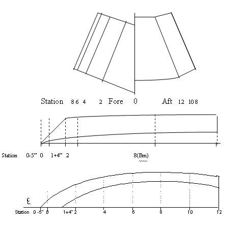
Figure 1
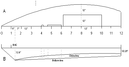
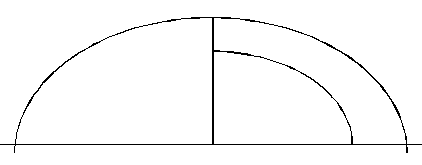
Figure 2
Well, the modifications in Profile
and Half-Breadth drawings are easy. But the compound curves of
the bottom in Body view are difficult to copy for plywood. The
best that can be done is illustrated in figure 3.
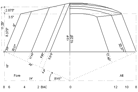
Figure 3
In the drawing are the following
changes
1. The side panels are
cut off level with the deck.
2. The width of the side panels at Beam is reduced to 9".
3. Across, the bottom is rounded. The bottom camber at Beam
is 2.875" (2 7/8)".
4. The camber is constant over the whole length of the bottom.
5. Longitudinally, the bottom centerline is a straight line
to prevent compounded curves in the plywood bottom panel.
6. The vertical transom is 10.25" at the
center of its crown. The frames become ¼"
higher per station toward fore. At station #2 the height of
the frame is 12.75". At dead center at
station BAC, the distance between deck and bottom is
12.9".
7. The decks beside the cockpit are widened to 12".
8. A dagger board replaces the centerboard.
9. The deck fore is made longer to behind the dagger board box.
10. The deck aft is 24" long.
11. There are no coamings around the cockpit, just a finishing
edge.
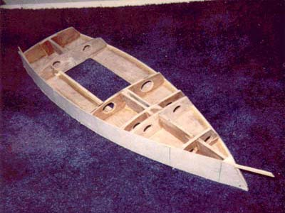
Hull Construction
The method of construction is different. Build the hull from the
deck up.
Deck
1. With the good side under,
put a 4'x5' board of 1/8"
Philippine mahogany aft against a 4'x7' board
to make the 12' deck.
2. Temporary, secure the panels in this position longitudinally
with two 1" slats 32"
apart with ¼" screws with a round
head.
3. Draw the longitudinal centerline on the panels, and the ten
station lines at 12" intervals.
4. Plot the deck contour line with the measurements shown in
figure 3.
5. Where possible, at a distance of ½",
draw a second contour line outside of the first line.
6. Cut off the excess outside of the second line.
7. From a piece of scrap wood, make a right triangle with legs
12" and 5". Place
the short leg on the table of the table saw. Set the blade at
22.62º against the hypotenuse of the template.
8. Rib a 13' batten of 1"x2"
finished lumber of knotless pine, or spruce at the angle of
22.62º. Check that the two battens are
perfectly equal. If not, take the thinnest batten. Adjust the
guide against it. Run the other slat through for a second time.
9. Soak the battens for 24 hours in water in a 4"
ID plastic rain pipe, 14' long, and
closed off with a cap on one end.
10. With the beveled side on the outside, clamp the wet battens
along the inside of the first deck contour line. Work slowly
and precisely. See figure 4. At station #8, keep the battens
1/8" inside of the plotted sheer line
to allow for the bevel of the sheer line deck edge.
11. At the bow, cut the first clamped batten flush with the
opposite sheer line. Miter the second batten against it in a
tight fit. Do not cut the overlapping ends at the stern yet.
12. If the battens are too stiff for the bending onto the deck,
let them dry first. Make small partial kerfs 3", or 4"
apart. Soak them again, and clamp them onto the deck.
13. After they have dried overnight, glue them onto the deck
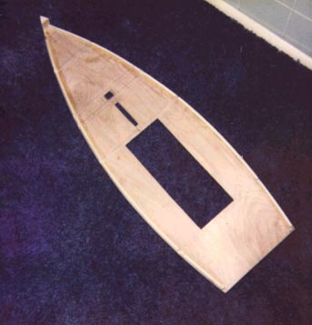
with plastic resin glue. See figure 4, and the photograph.
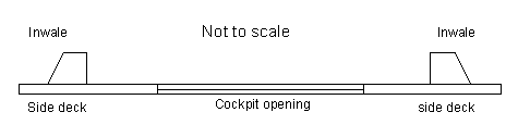
Figure 4 Inwales
glued onto the deck
14. With a utility knife remove
the ½" excess outside the glued-on
inwales. Hold the knife against the beveled battens. To prevent
tearing into the grain, start at Beam, work towards the bow
and the stern. Make sure to cut at bevel angle without cutting
into the inwales. Make the first cuts very lightly.
15. Cut the hole for the mast, the slot for the dagger board,
and the cockpit opening.
16. Cut off the overlap of the inwales at the stern 1/8"
fore of the end of the deck. See the photograph.
Cross Frames
1. Make 1/8"-wide
cuts into the inwales fore of and against the station lines
#2, #4, and #6. Be careful not to cut into the deck. See the
photograph.
2. Make the same cuts in the inwales aft of and against the
station lines #8 and #10.
The cross frames are made from
1/8" Philippine mahogany. Start with frame
#8.
1. Cut a rectangular panel of
14"x50". Draw a vertical middle line
on the panel.
2. Place the panel into the inwale cuts at station #8. Line
up the vertical middle line of the panel with the centerline
on the deck.
3. Mark the exact width of the panel at the sheer lines of the
deck.
4. Remove the panel. Draw the camber line of frame #8 on the
panel as shown in figure 5. Cut out the panel.
5. Cut all the other panels in the same way by first marking
their exact width while they are positioned in the inwale cuts
on the deck. Take the bend of their crowns from the first
cut panel #8. See figure 5
Take the sizes of the bevel angles
of the sides of each frame directly from the deck when the width
is measured.
Note that the crown line of each
frame is lined up with the crown line of frame #8. Their exact
heights are measured on the vertical middle line from the crown
line down. That way the curve of the crown line is the same for
all the frames.
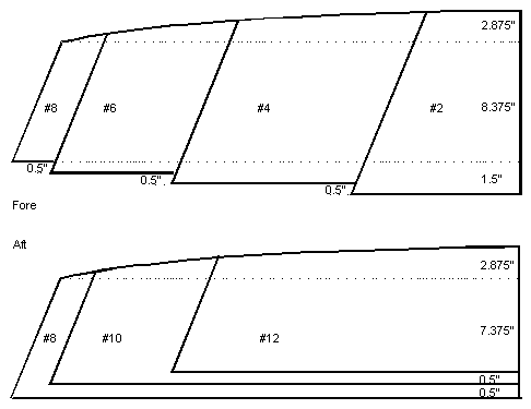
Figure 5 Half-Body
view of the cross frames.
Longitudinal Frame Fore
1. Make a 1/8"-wide
cut in the inwales over the centerline at the bow.
2. Cut the longitudinal bow frame to the measurement of figure
6. Note that the highest point of the bottom (12.9")
is at station BAC.
3. Place the frame between the tip of the bow (station #0) and
frame #2.
4. Glue a piece of 1"x1" on the deck
between the inwales and the frame at #2 station.
5. Glue a second piece of 1"x1" on
the opposite vertical side of the bow frame.
6. Temporary, attach the bow frame to the 1"x1"
on the deck with round headed, ¼"
screws.
7. Place the cross frame #2 in the slots on the deck. Attach
frame #2 in the same way to the vertical 1"x1"
of the bow frame.
If the frames are lined up perfectly,
both frames stand absolutely perpendicular on the deck, and perpendicular
to each other. The sides of frame #2 are flush with the curve
of the deck at the inwales.
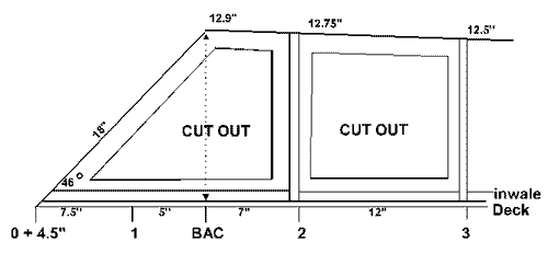
Figure 6 Longitudinal
bow frame
Longitudinal Frame Aft
The longitudinal frame aft
is placed between the bulkhead at station #10 and the transom
board at station #12. The measurements are taken directly from
the setup. Cut out the middle of the frame to reduce weight. Check
for a perfectly perpendicularity to the bulkhead, the transom
and the deck. Attach the frame to the deck, the bulkhead, and
the transom with pieces of 1"x1" just
as the bow frame fore with temporary screws.
Dagger Board Box
Install the 18"-long
dagger board box fore of the bulkhead at station #6. The dagger
board box trunk aft is attached fore against that bulkhead. Use
1"x1" pieces of lumber to attack the
box to the deck. The method of construction of the of the dagger
board box is the same as the method of the building of the centerboard
box of the skiff. The width of both boxes is the same also. The
difference is that the bottom line of the skiff is curved. The
bottom line of the car-topper is straight.
Mast Box
The mast box is set aft of the
X-frame at station #4. The four walls of the box are made of 1"x1"
plank. Inside the box is 3" wide. Close
up the mast box with a cover of the same wood to protect the bottom.
The photograph shows two frames, one, fore and one aft of the
box. This extra frame aft of the mast box can be omitted. Instead,
make the sides of the dagger board box long enough to anchor them
onto the mast box.
The longitudinal frame between
the X-frames at station #2 and station #4 seen in the photograph
can also be left out. In that case, glue a piece of 1"x2"
over the centerline onto the deck instead. The holes in the frames
#2, and #4 can be made a lot bigger to reduce weight further,
and allow for better air circulation. Make the holes in bulkheads
at station #6, and #10 round. On the water, these holes are closed
off airtight with conical plastic cups to create two flotation
chambers. A longitudinal frame attached to the carlins and the
bottom on each side of the cockpit between the bulkheads fore
and aft will add two additional flotation chambers, making the
hull practically unsinkable. Make round holes in these panels
that can be closed off airtight also. When the boat is stored
on land, the cups are removed for ventilation.
Bow
Gussets
The bow
gussets are ripped from 1"x1"
lumber. They are glued on each side fore the longitudinal bow
frame.
1. Miter
two pieces of 1"x1" at the same angle
as the bow angle of the longitudinal bow frame. See figure 6
2. Place the lumber against the frame on top of the inwale on
the deck.
3. Mark the inwale line on the lumber.
4. Rip the lumber at this bevel angle.
5. Repeat this for the other side.
Chines
The first bevel of the chines
is ripped from a 1"x2" in the same
way as the sheers. The angle of the second bevel is equal to the
angle between the side of X-frame #8 (Beam) and the bottom curve.
It is taken from this frame.
Chine Notches
Making the notches for
the chine battens is a precise job. Remove the temporary placed
X-frames and bulkheads from the deck. The chine batten must fit
perfectly flush with the sides, and the bottom line of the frames.
The easiest way is to undercut the notches slightly and then file
them to the exact size.
Cut off a small piece from the
chine batten. Use it to check the correct size of the notches.
Placing the Chines
1. Glue all the prefabricated
parts onto the deck. Double-check that they are all perfectly
perpendicular to the deck, and to each other. Be finicky about
this!
2. Secure the dagger board and the mast foot box extra with
stainless steel screws to their trunks and the frames.
3. Line the transom frame #12 fore, and the bulkhead #10 aft
with a piece of 1"x1" along the bottom
curve on each side of the longitudinal frame.
4. Do the same with bulkhead #6 fore on each side of the dagger
board box, and with the X-frame #4 aft besides the mast foot
box.
5. Place a perfectly straight 1"x2"
batten on its narrow side over the frames on the centerline.
Check is the frames heights are correct. Correct small mistakes.
6. When you are satisfied with the lineup of the setup, place
the chine battens in the notches. Glue them against the frames
and their linings.
7. Check for any humps, and/or hollows in the chine line. Correct
small discrepancies.
8. Make a 1/8"-wide, and 2"-long
vertical saw cut into the Beam frame #8 on each side beside
and against the chine battens on the cockpit side. These starter
cuts make it easy later to remove the middle part of the frame
that blocks the cockpit.
Carlins
Attach the 1"x1" carlins onto
the longitudinal sides of the cockpit between the bulkheads #6
and #10.
Optional Extra Flotation
Chambers
Install the vertical walls of
the extra chambers against the carlins and the bulkhead.
The bottom edge is flush with the bottom curve of the bulkheads
to which they are attached with vertical pieces of 1"x1".
Line the bottom side of the panel inside also with 1"x1".
Sand the 1"x1"s flush with the bottom curvature.
For ventilation, cut two round
holes in each panel as shown in the photograph in bulkhead #10.
Side Panels
Each side panel is made
up from two boards: a 16"x 96" (8')
board aft and a 21"x60" (5')
board fore. The board aft is lined up with the transom. That places
the 4" wide joint of the board between stations
#5 and #4.
Installation of the Side
Panels
1. Cut a 4"x 16"
butt strip of 1/8" Lauan.
2. Cut 4"-wide, 1/8"-deep notches
into the chines and the inwales in the middle between station
#4 and #5. Make sure not to cut into the deck.
3. Place the butt strips into the notches. Cut them flush with
the chines at the bottom side. Make sure that they blend completely
and perfectly fair with the chine and the deck lines. Draw the
vertical middle line on the strips.
4. Attach temporarily 4.5' of 1"x1"
under the deck at station #8 (Beam). The 1"x1"
protrudes 3" on each side of the deck.
5. Place the aft panel on the protruding part of the 1"x1".
Place a C-clamp on the lumber against the panel to hold the
board firmly against the setup, but can still be moved.
6. Attach the panels against the inwales and the chines with
temporary screws at the stations from aft toward fore.
7. Mark the location of the vertical middle line of the joint
strip on the side panel. Cut off the excess of the side panel
with a utility knife. It is not necessary to take off the panel
from the setup. Just hold a piece of scrap Lauan under it to
protect the strip while you make the cut.
8. Draw a pencil line along the chines and the deck on the side
panel board. Cut off the excess above the chine and under the
deck. It can be done on the setup with a snap-off utility knife
by extending the blade as far as possible. Work slowly, away
from the grain. Put hardly any pressure on the first couple
of strokes. The best tools for this kind of a job are a veneer
saw, or a Japanese flush-cutting saw. A second way is to take
off the panel and cut along the lines with a jigsaw set at the
flare angle. Take your time. Aim for a perfectly fair
line. Correct small discrepancies with a file, or sandpaper.
9. For attaching the side panel board fore, you need a helper
to hold the board against the panel aft at the joint between
stations #4 and #5 while you align the height of the panel,
and place the temporary screws at the joint. Again place the
next screws by working from aft to fore.
10. Draw the lines and cut off the excess above the chine line,
under the deck, and fore of the stem.
11. Once you are satisfied with perfectly cut and placed panels,
tape the top edges of the chines with masking tape to prevent
spilled glue spots on these battens.
12. Glue the panels with plastic resin to the chines, the inwales,
the butt strip and the X-frames. Use roundhead screws at regular
interval where it is not possible to use clamps. To prevent
dents, use cardboard washers between the screw heads and the
wood.
13. When the glue has dried, remove the screws; overfill the
holes with wood filler. When dry, remove the excess with fine
sandpaper. Remove the masking tape from the chines.
Bottom
The bottom is made up
from two boards. The first board is 8' long.
One edge is lined up with the heel of the stem. The other edge
comes to nearly 5" aft of station #9. The
second panel is jointed to the first panel with a 4"-wide
butt strip also.
Installation of the Bottom
Panels
1. Place the 4'x8'
panel on top of the setup. Align the front edge with the heel
of the bow stem. Hold the panel in place with a temporary roundhead
screw.
Make sure that the longitudinal middle line of the board is
lined up with the centerline of the hull.
2. Mark the place of the panel edge aft on the chines. Remove
the panel and make 4"-wide, 1/8"-deep
notches in the chines, 2" on each side
of the mark. Make sure not to cut into the side panels.
3. Replace the bottom panel. Over the middle line, attach the
board with the temporary screws with the cardboard washers to
the frames. Work from fore toward aft.
4. Attach the bottom panel to the chines with the temporary
screws. Do not attached one side completely to the chines first
and then the other side, but work both sides from fore to aft.
5. Draw the bottom contour line on the underside of the panel.
Cut off the excess in the same way as was described for the
side panels.
6. Cut a 4"-wide strip of 1/8"
Lauan that fits exactly into the cut notches when it is given
the bend of the bottom curve.
7. Draw a longitudinal middle line over this joint strip. Put
resin glue on the side fore of the line. Clamp the strip under
the bottom panel. Let the glue dry. The joint line is approximately
4.75" aft of station #9 (station line
#9 + 4.75").
8. Place a 3'-long board aft against the bottom
panel fore. Attach and glue it in the same way to the frames,
the chines and the transom. Work from fore toward aft. To hold
the panel tightly to the joint strip, use the round-headed temporary
screws with the cardboard washers while the glue dries. Cut
off the excess.
Staggering
Note that the deck joints
are in the narrow parts of the deck. The joints in the side panels
and the bottom are staggered away from the deck joints
as far as the material permits.
Transom Reinforcement
Cover the transom with
an additional panel of 1/8" Lauan that overlaps
all the seams with the deck, the side panels, and the bottom by
1". Cut off the excess.
Sealing the Seams and the
Joints
Seal all the seams and
the joints with Buckram tape and resin glue (urea formaldehyde).
Finishing
Glue in the 1/8"x1"
bottom slats
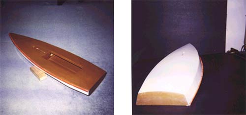
Painting the Hull
Paint the hull with the colours
of your choice, but make sure that they are highly visible. The
secret of a good paint job is not in the use of expensive marine
paints, but in careful preparation.
To prevent eye glare, use a
flat paint on the topsides.
Use non-skid porch paint on the bottom inside the cockpit.
Rudder
The rudder for the car-topper
is a kick-up rudder.
Gunwales
Rip the gunwales
at a flare angle from a 13' - 1"x2"
batten. Plain varnish them, or paint them in a contrasting, bright
colour. Screw them to the hull after the hull is painted
Trial Rigging
Before you spend a lot of money
on rigging, make a mast from a 12'-2"-ID
PVC pipe with a 12' - 2"x2" slat stuck
inside the pipe. Make a lugsail, from a 10'x12'
polyethylene tarpaulin. With this trial rig you will find out
how the boat performs
Total costs
Without skimping on the hardware
and the fittings you will stay within your budget of Can$400.
For this bargain, I got three times as much fun than from buying
a real Laser: First, the fun of building the boat, second, the
pleasure of sailing the boat, and thirdly, the fun of “laughing-all-the-way-to-the-bank”
by saving myself 95% of the costs. Not a bad deal IMHO.
Barend
Migchelsen
(Click
here to go to Barend's book page)
|