|
Designing a Safari Boat |

|
|
By Milton "Skip" Johnson - Houston, Texas - USA |
|
Editors note: Skip sent us some construction pictures of his design for a six man canoe and an article about the theory behind designing such a boat - both submissions are mixed together below.
|
|
First a disclaimer. Never, ever in the annals of human endeavor has there been a canoe that ‘won’ a race. Paddlers win races. The canoe is the tool these guys and gals use in an almost superhuman event called the “worlds toughest canoe race” a.k.a. the Texas Water Safari. This article is about designing the best tool I’m capable of.
The dry statistics of the Safari are a pale image of the effort involved in campaigning a Safari entry but it’s a start. 260 miles, nonstop (don’t even slow down) to win. Everything you need must be taken with you, except water and ice, if it breaks, it’s broken. A lot of dams to portage early in the race, along a twisty narrow San Marcos river. Plus a lot of night paddling through log jams with Texas sized biting critters capped off by a final open water run across San Antonio bay which can be daunting when the wind blows. All this happens in the heat of a South Texas June. Tough Race.
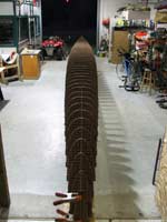 |
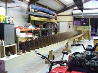
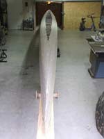
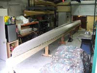
As promised here are some pictures of the 6 man Texas Water Safari Canoe that George Melder is building in his usual quick and meticulous manner. Some of the details of the design are somewhat proprietary; the team spent a few dollars for the computer time to minimize drag in a variety of conditions, particularly shallow water.
(click images for larger views) |
|
When asked to help design a new canoe for the race the first question is “how much is it all going to weigh?” Next, “what kind of time are you wanting to finish in on a good year?” That’s about it. Usually these are solo unlimited, tandem unlimited or plain old unlimited, now 6-man maximum. I love unlimited, there are no restrictions regarding length, beam, etc. anything goes as long as it is human muscle power. It is actually pretty simple once a speed range is determined and a midsection agreed on.
The midsection is the thing, if our theoretical paddlers had infinite balance a semicircle would be perfect, optimum volume/surface area ratio, minimum beam and minimum weight. But our paddlers are human and need to sit up with their tailbone 5-7” above their heels for maximum comfort and endurance. Time and experience has led to midsections about four to five times as wide as they are deep of a superelliptical shape.
Second disclaimer. I’m reminded of my all time favorite cartoon, two guys shaking hands across a desk, the respective thought balloons “You Pathetic Techno-Moron” and “ You Pathetic Computer Geek”. I’ve stood on both sides of that desk many times and in many ways. Some of the following may seem esoteric to some and simplistic to others, but it’s the way my mind works.
| I can tell you its 44' long and George had to extend his 40' shop a bit to fit the whole boat in. In order to get the pictures, George had to get on a ladder outside the shop, and you can get some idea of the scale by looking at the tandem canoes racked on the wall. |
|
|
Back to superellipses, a superellipse is an ellipse (x^2 +y^2= 1) that’s described mathematically just like a normal ellipse except the exponent is some number other than 2 (usually larger). Incidentally a superelliptical egg with an exponet of 4 or more will balance on its end, looks impossible but it will. There are an infinite number of other shapes that are probably just as good perhaps even better, but a supperellipse is an elegant, mathematically pure form that is easy to manipulate and works well as a canoe cross section.
Archimedes will not be denied, for a given weight, there is a definite amount of water that must be displaced. In the power and speed range we are talking about here, the Prismatic Coefficient wants to be about 0.50 (more on this later). Once, some years ago I designed a boat for someone that wanted a given length and cross-section that forced the prismatic coefficient up a little bit. It wasn’t a bad boat but you could tell from a number of little clues that it would have been happier in the groove.
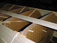 |
The boats being stripped in medium density Divinylcell (5#) 3/8" thick. The skins will be a combination of carbon and kevlar.
The glue is polyurethane (gorilla glue) the only application I'd consider for that particular glue. |
|
Rather than ramble on let’s do a hypothetical example to make it easier to follow and have some concrete if bogus numbers. Our bogus safari boat (BS3) is a three man boat, the possibility of someone really wanting a three man unlimited boat is fairly slim since they would be competing with 4, 5 and 6 man boats and there is some truth to the old saying “ there’s no substitute for cubic inches”. Actually I believe the Achilles heel of a 3-man boat is the amount of wetted surface each paddler has to pull through the water.
BS3 will weigh 640 pounds and run with the big boys (8-mph). Weight is 485# paddlers, 60# gear and 95# boat. BS3 will displace 10.26 cubic feet of water and will want to be about 30 feet long. At this point I would usually convert all the parameters to metric and run some optimization routines in Michlet www.cyberiad.net/michlet.htm but that is standing way over on one side of the desk down at the far end of the hall. For the truly hydrodynamically obsessed, Michlet is an excellent free CFD program (workbench) from Leo Lazauskas that includes an evolutionary optimization module, Godzilla to minimize drag.
| The trick apparently in using the glue is to mist the joints with water, I'm trying to figure out the simplest way possible to do that since I'm going to do a foam strip of the EasyC but just e-glass. The canoe team likes to use Marweld epoxy a fairly standard 2/1 mix. |
|
|
Back to the boat. 30 feet long 10.26 cubic feet means a mid-section area of 0.684 square feet. This area would fit into a rectangle of about 0.91 square feet or 131 square inches. This translates into a depth and beam of 5”x 26” more or less. 26” maximum beam is a little narrow to my way of thinking and would try to sell my hypothetical client on a little more beam (27.5”) giving a depth of 4.75”. Twenty-seven and a half inches would be ridiculously wide for a sprint boat but this isn’t a sprint race. On to the drawing.
The drawings are created using AutoCad 14, tool of choice in my day to day job as an Architect. Twenty plus years ago I designed my first mathematically inspired canoe using A SuperCalc spreadsheet on an Osborne portable computer, then hand plotted sections full-size from reams of coordinates. It was tedious at best. Over the years as computer aided design developed, I created some small Autolisp routines (macros) that worked inside AutoCad to create the curves I was looking for. Besides superellipses for cross sections the longitudinal curves are parabolas. I love parabolas, the most elegant of curves. Another mathematically pure curve the parabola is also amenable to manipulation of the exponent to vary the shape of the curve.

click icon above for PDF drawing BS3
First the midsection. (drawing BS3) You may need to zoom in on the midsection a little bit to see some of the dotted lines, I don’t have a lot of control over my little PDF printer output (primoPDF), but it’s worth every penny (free), kind of like this article. The dark dashed lines are for a true ellipse (n=2) and a box (n= infinity). In between are curves for n= 3,4 and 5. The section selected displayed in red is probably a little too “fat” and 3.8 or so would be slightly better, but this is just an example, nobody's going to paddle it. The curve back in above the waterline has absolutely no hydrodynamic significance, but the paddlers keep insisting that the gunnels be as narrow as possible so they can put their blades in the water right next to the boat. In this case the curve starts coming in a little bit too close to the waterline and the final sections would be just a little bit different.
Moving down the sheet, the next section of the drawing is the preliminary layout of the lines, plan, profile and curve of exponents. Plan and profile are pretty self-explanatory; curve of exponents refers to the bottom curve that represents the changing exponent from the midsection (4 in this case) to the ends (2 in this case). Using the same exponent throughout the hull would result in a very bluff (full) hull. The midsection is actually a little behind the geometric midpoint to account for the overhang at the bow and just because. Usually the midsection wants to be within one or two percent of the midpoint of the waterline length, based on innumerable computer simulations (Michlet and Godzilla) and a few earlier unfortunate but educational boats by and for yours truly. The longitudinal curves are parabolas, in plan the forward curve has an exponent of 1.60, the aft 2.0. In profile the keel line exponents match the sheer and the sheer line is 2.0 in both directions. Having the keel line come all the way to the waterline is probably a mistake but theoretically gives the most efficient hull with least wetted surface and drag. I can usually convince a client to get within an inch or so of that ideal and the differences are pretty nominal. The curve of exponents in this case is just a simple arc, though usually I’d use a parabolic curve.
 |
George and I think its a little too thick but its not our boat. When and if I ever did a really hi-tech boat I'd use some of the epoxy the aircraft builders use.
|
|
After the preliminary layout is done the magic of tediously developed macros is invoked and the work is almost done. In this case I’ve used a station spacing of 12 inches, though usually I’d recommend 8” for a real boat. Its not that many more stations to cut out, which isn’t that hard with full size plotted patterns. If the boat’s going to be built with foam strips, you should use the closer spacing. What the macro does is starting at the midsection of the boat it gets the length of the half breadth of the hull, depth and exponent and draws that station then indexes down and does the next one and plots two curves as it goes. One is the area of each midsection and the other is the perimeter of the section (below the waterline). Those two curves tell the tale of the boat. The magenta line represents the curve of areas of the sections and the area under the curve represents the displacement of the boat. In this case I’m off by almost nine percent, 9.42 cubic feet instead of 10.26, Normally I’d redo the design, lower the rocker an inch or so and fatten up the ends a little bit. On this one never mind. The wetted surface area, 77.75 square feet works out to 14.9 square feet per paddler. For reference, the C100 doubles boat that Chuck and I paddled last year in the Colorado 100 had 17.5 square feet per paddler when the boat was dry inside, e.g. a purely theoretical number. A six man safari canoe might have 12.5 square feet or so per paddler.
One last thing, that prismatic coefficient. The dashed box along with the curve of areas is the same width as the midsection and its area represents a volume of the midsection extended to the ends of the waterline, in this case 19.84 cubic feet. 9.42 divided by 19.84 gives a prismatic coefficient of 0.475, a little less than the 0.50 or so we were shooting for. The magenta curve closely represents a profile called a trochoid which is the shape of an open water wave and has that same ratio of 0.50 of area under the curve verses the boundary box.

click icon above for PDF drawing "Example"
I was going to finish up this design with the shaping of the tumblehome, offsets for type construction etc, but don’t have that much fire in my belly for a hull that’s not quite right and isn’t going to be built. So I leave you with an image of a doubles boat that was built and served her paddlers well. (example)
Skip

Other Articles by Skip Johnson:
|