| by Craig McEwan - Queensland,
Australia |
My boat building project got underway in February
2004 with the arrival of my plans and I started construction
in April 2004. I’d been building radio controlled
yachts from 600mm monohulls to 2m Trimarans, and all
sorts in between for a number of years to fill the
need after selling my 27’ Choey Lee. I bought
it while working in Fiji and spent the best part of
a year with the family sailing it back to Queensland.
The people you meet and the places you go stay with
you forever, and the dream lives on.
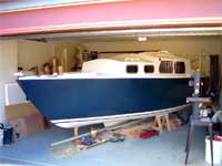 |
My boat
building project got underway in February
2004 with the arrival of my plans and
I started construction in April 2004.
(click
images to enlarge) |
|
Anyway I wanted to get back into “real boats
“, not to do blue water sailing but be able
to have regular weekends away, and with Moreton Bay
and the Gold Coast Broadwater at hand, all I needed
was something easily handled, that you could also
get out of the sun. I had in mind what I wanted, the
layout, the look, and what I didn’t want. One
thing I didn’t want was a centreboard case in
the way. Another thing I didn’t want was a hard
chine. If I was going to build a yacht I wanted to
have a go at something different. I decided on a Bruce
Roberts 19 in version “B”.
A fixed keel Double diagonal ply cold mould 20 footer.
This I could fit corner to corner in my double garage
and be able to work on it day or night, rain (still
waiting) or shine. This was a boat plenty big enough
for me to single hand, and take the family as well.
I don’t have the yard room to park a boat and
trailer so this is a boat that will live in the water.
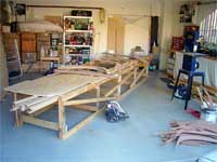
I started driving around the new housing developments
collecting scrap 3x2’s and 4x2’s and soon
had enough to build the strongback. Then it was off
to see Ian Philips at Bote Cote for the sheets of
ply, stringers, epoxy etc. We had talked several times
on the phone, and his book explaining Bote Cote products
was very informative. I’ve found Ian to be very
helpful and always keen to know how it’s going.
| I started
driving around the new housing developments
collecting scrap 3x2’s and 4x2’s
and soon had enough to build the strongback. |
|
|
After going over the plans a few times making the
changes I wanted to suit me, and where I would be
sailing it, then discussing them with Paul, from Bruce
Roberts International and adding his alterations to
compensate, I laid up 18 sheets of 4mm ply and ran
down the lot with the skilly cutting them into 150mm
strips by 2400.
The frames for this boat are in two types, Permanent
and temp. The perm frames I cut out two layers of
9mm x 70mm ply and saturated and glued with epoxy,
then gave a couple more coats. The temp frames I made
out of anything as they are only there to hold shape.
The stem was cut from 3 layers of 12mm by 180mm, glued
and coated the same as the frames. All joints in the
laminating were offset.
Once the stem and frames were up, the keelson, two
layers of 20 x 150mm x 6m, were glued and screwed
from stem, the perm frames to the stern. A piece of
plastic was laid over the temp frames where the keelson
was set into it so they wouldn’t stick. This
was then epoxy coated. Once they were all in place
on went the stringers, glued, screwed and epoxyed.
The Gunwhale stringers are double 45 x 20 from stern
to midships then three layers from midships to join
the stem at the bow. I used an electric plan to shape,
or plane, it back to two thicknesses at midship. Again
these had plastic under them at the temp frames. The
next job is onto the planking.
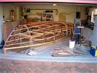 |
The Gunwhale
stringers are double 45 x 20 from stern
to midships then three layers from midships
to join the stem at the bow.
|
|
The first layer goes on at 45deg to the gunwhale
starting midship and I would hold it in place with
some hand clamps and the lay up two either side of
it to mark what needed to be shaped off so they would
butt together when laid across the stringers. I would
then do the same on the opposite side so the planking
was kept even both sides. If you plank one side first
you can build twist into the hull. I found I could
mix enough epoxy / filler to fix five planks aside
before it went off with no waste. I attached the planks
using a staple gun and compressor and placed 40mm
cut lengths of blue woven packing tape under the staples
so I could pull them out with pliers later. I would
go around collecting used packing tape from businesses
and sit at night cutting piles because I wasn’t
shy in using staples.
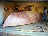
I was surprised how easy the planking went on. After
I’d marked what needed to come off and numbered
the ten planks, five aside, I’d cut them all
with a band saw, The best tool I’ve ever bought.
And if they needed it I use a small hand plane. You
soon get very good at cutting them. When the first
layer was finished, trimmed, and all the staples removed,
a fun job, not, I climbed under it and ran a strip
of masking tape down each butt join so that when any
epoxy filler was used in a gap, after it went off
I could peal off the tape and have a smooth finish
inside without sanding it. The hull was saturated
with a diluted coat and given another coat of epoxy.
Then the second layer was put on the same way at 90
deg to the first. This time the epoxy / filler was
brushed on so the second layer had no gaps or air
between it. You end up with an incredibly strong light
hull, and with a layer of 200gm woven fibre glass
over that it finishes up around 10mm thick. It only
took me two full weekends to plank both layers, and
I was working on my own.
| I was surprised
how easy the planking went on. After I’d
marked what needed to come off and numbered
the ten planks, five aside, I’d cut
them all with a band saw, The best tool
I’ve ever bought. |
|
|
While I was waiting on epoxy drying, I would get
on with other things like the Rudder and Tiller and
started building the keel. I changed the way my keel
was to be made, because I was building in my garage
I couldn’t fit the keel as plan or I would never
get it out the door, so I had to made it in two pieces.
The keel is 2400 long by 700mm deep. My plan was to
split it so I had a piece 300mm deep, I could then
glue and bolt to the keelson. This also gave the hull
something to sit on after it was turned. The other
piece I’ll slide under after it’s out
the garage.
Some of the changes I made to the plans are: version
“A” has a centreboard and side decks but
the hull has 100mm less free board. Version “B”
has Knuckle flats ( a flat side section like an additional
chine were the hull tilts back inwards and joins the
cabin sides and no side deck. I incorporated parts
of A with B by continuing the lines of the frames
because I wanted side decks. I’ve passed climbing
over cabin tops to get to the bow. This also gave
me an extra 100mm headroom.
I then stepped the coach roof another 120mm almost
to where the mast steps and it’s resulted in
almost full head room over the galley area with a
well balance look, to me, with a clear cabin sole
on a 20 footer.
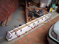 |
My plan
was to split the keel so I had a piece
300mm deep, I could then glue and bolt
to the keelson. This also gave the hull
something to sit on after it was turned.... |
|
I made some other changes too. it originally had
a vee birth and two ¼ berths under the cockpit
seats. I reduced the length of the cockpit 250mm (10”)
and increased the cabin size and sacrificed the starboard
¼ berth. I still have plenty of seating space
in the cockpit for the amount of people I’ll
have onboard, or to stretch out and relax. I added
an icebox next to the cooker and good size cockpit
locker, which we will go into later. I also added
a Sampson post if it’s going to moored.
Most of my sailing will be shorter trips, and more
at anchor enjoying the splendours of the islands around
the bay, so I wanted more comfort and to be more airy
below to suit Queensland weather.
I’ve dedicated all my weekends to building
since the start, including a couple of weeks full
time at Christmas and the only help so far was turning
the hull. It’s taken 18 months to date and I’m
close to painting. Had I done bits here and there
it would have dragged on and maybe lost interest so
I was determined to keep at it so I could sooner be
away on some Leisurely “ARINAR”.
| ...The other
piece I’ll slide under after it’s
out the garage. |
|
|
So the second layer of ply is finished, sanded, and
coated with epoxy, and on to the keel. I used a piece
of 20 x 150 x 2500mm as a template, which would also
be the top plate when the keel is fixed to the hull.
I marked its position and the keel bolt positions
and the shape the keel will finish. It’s 140mm
wide at the widest point so I bevelled its edge to
the hull. I packed up the back of the template until
it reads level, that gave me the size and shape of
the wedge I needed to fit between the hull. With the
amount of plan sheets and information you get with
these plans you can’t go far wrong, anyway I
epoxyed two 75 x 50’s together, roughed it to
shape and finished it with a belt sander, then epoxyed
it to the hull. Now I was able to work on a level
surface.
A friend gave me a part sheet of 45mm thick marine
ply he’d used to replace his power boat transom,
so I marked it 300mm deep, cut it, and epoxyed it
together. I used the electric plane to tapper the
ends. I also got hold of some lengths of laminated
hard wood that was the right width for the rest of
the keel minus the ballast section. The double piece
of 300mm deep-laminated ply was epoxyed to my template
as this part of the keel was going to be joined to
the hull so that when it was turned it could sit on
it. I then drilled the boltholes through this piece,
positioned it on the hull and drilled those. I put
the two keel pieces together, marked and drilled the
other. To make the keel easier to shape I epoxyed
30mm high density foam to the side and filed it back
to the shape I wanted, with a good result. This was
then coated with epoxy. I epoxyed and bolted the section
to the hull.
The next job was to cover the hull and keel with
200gsm woven fibreglass. It’s a job better tackled
by two, but, since that was not to be, I laid the
cloth over the lot, held it in place with masking
tape and worked my way around doing a drop at a time.
After this a layer of epoxy / sanding filler was screed
over and sanded then a coat of Bote Cote 2 Pac primer
was brushed on. Definitely should be sprayed as I
ended up screeding another layer over the top to get
the finish I want. Now the time we all look forward
to, The turning over.
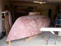 |
You end
up with an incredibly strong light hull,
and with a layer of 200gm woven fibre
glass over that it finishes up around
10mm thick. |
|
So the day was planned, the lads were all called,
I’d been to Bridgestone to get a pile of old
tyres. I’d made up a trolley to wheel it back
down the drive into the garage after it was turned.
I put three braces across the Gunwhale with chocks
both sides so it would be rolled on those not the
hull and waited for the blokes to turn up.
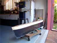
Everyone was on time and it took no time at all.
I’d been under the boat and unscrewed the frames
from the strongback, she was up and out before I could
grab a corner. Out into the middle of the street,
put the tyres under and over she went. A historical
moment, and captured on film. The first look inside
the hull right way up, wow it looks big. The trolley
was awkward so it ended up being carried back and
positioned in the garage.
After a couple of beers and everyone had gone I started
measuring and marking what would be were. Of the original
eight frames only three remained, 2,3 and 4. 2 and
3 had the supports for the vee berth attached before
they were placed on the strongback. 4 comes mid cabin.
Two additional ones were to be laminated up in position,
5 and 6. 5 being the end of cockpit / cabin bulkhead,
and 6 being mid-cockpit. Number one was to become
the bulkhead for cabin one side, chain locker the
other. I had decided to shorten the cockpit 250mm
(10”) and increase cabin length to fit in a
ice box and good size table.
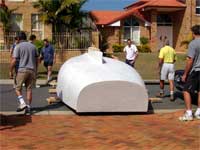
| So the day
was planned, the lads were all called, I’d
been to Bridgestone to get a pile of old
tyres. I’d made up a trolley to wheel
it back down the drive into the garage after
it was turned. |
|
|
I’ve got a good deep chain locker, with the
hatch through the bulkhead, then the vee berth, with
a forward opening hatch above it, to get the breeze,
with a splash guard around it. Then to starboard,
a sink, two-burner gimballed cooker and the ice box.
To port I have a fixed table 900 x 500 x 70mm deep.
The front hinges down to give me flat chart storage
and an internal draw for rulers, pencils, hand held
g.p.s. etc. Above the table is the radio’s,
cd player, switch panel, digital battery monitor and
two cigarette jacks which are panelled in the cavity
between the table and deck. Under the table against
the vee berth is a locker and behind an area to hold
the porta potty. There is stowage under the vee berth
and a 50lt water bladder. Behind this is the port
quarter berth, which forms the other seat. A lot of
boats store the Porta potty under the vee berth. That’s
one thing I didn’t want under my head at night.
You hear enough of that through the day without having
to sleep on it.
The first job was to apply a dilute coat of epoxy
over the interior then a second coat undiluted, and
I then put on another coat halfway up the hull in
case of water while on a heel. So back to laminating
frames. Once I marked, and measured up the length
from gunwhale to gunwhale, I then cut the strips of
6mm x 25mm across the sheet to finish 7 laminations
high. I pencil marked the hull mixed the epoxy / filler
and started from one gunwhale working across to the
other, stapling them to the stringers as I went.
I got hold of some 20 x 60mm hard wood to use for
the deck bearers which I laminated to both, ply knees
and the frames and also used stainless bolts. These
had cut outs for the deck carlins and cabin sides.
Once they were in place then came the cabin bulkhead.
This was epoxyed and filleted to the number 5 frame.
I kept the companionway opening high enough so that
with one wash board in, the top was above the cockpit
seats to avoid water getting into the cabin, and I
wanted to fit a manual bilge pump in the cockpit under
the companionway opening so I could reach it and the
tiller if I had to.
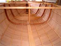 |
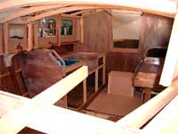
The first
look inside the hull right way up, wow
it looks big. |
|
Now that the deck bearer’s and cabin carlins
are in, and the bulkhead for the chain locker, the
vee berth is in, with storage hatches in it. It was
time to make and fit the deck beam, which will frame
the forward hatch opening. This was laminated from
two 12mm ply pieces then cut to shape. You cut a ply
template for the curve of the deck beams and a second
one for the curve of the cabin beams from the plans.
I also laminated up 12 pieces of 6mm x 72 mm to
make a 72mm square Sampson post, far stronger than
a solid piece, and nicer looking. I left a slot at
the base to straddle the stem and it went in with
plenty of epoxy. It was also bolted through the bulkhead
beam. I then framed and made the hatch opening. Because
I was changing the profile of the cabin sides and
stepping the coach roof, I had drawn the profile onto
paper, held it in place to make sure it was how I
wanted it then transferred it on to ply. Being a Pattern
Maker I did this with a number of jobs in the building
and have ended up with very little waste. Next we’ll
get onto the icebox, cockpit locker, wiring in LED’s
instead of bulbs.
I then framed up the bench top and cupboards and
made the table and chart draw. I cut the hole through
the bulkhead for the ¼ berth, framed and put
the base on. I then moved on to the icebox. If I was
going to the bother of making one, I wanted one that
would be efficient, so did a bit of research on the
net. What I ended up with was ply box well saturated
in epoxy, while the last coat was going off on the
out side, I rolled on a layer of cooking foil then
later epoxyed 100mm high density foam to the sides
and 110mm to the bottom. The lid also had 100mm on
it. The icebox fits up against the bulkhead so I stuck
a piece of foam 700 x700 x 100mm to the cockpit side
of the bulkhead so heat couldn’t penetrate.
The drain for the icebox is 12mm copper tube lagged
with it’s own through hull waste just below
the waterline with a tap so you can hold cold run
off in the line to stop heat penetration. It finished
up internally 300 x 300 x 350 deep. I’d sooner
reduce the size and have one that worked well than
a large one that didn’t, and I had limited space
to start with.
| It was time
to make and fit the deck beam, which will
frame the forward hatch opening. This was
laminated from two 12mm ply pieces then
cut to shape. |
|
|
Now it was onto the cockpit. The sole has a 25mm
fall aft with two 40mm drains straight through the
transom. The cockpit locker is to starboard with an
opening 300 x 800. It has a 40mm deep channel with
two drains that empty back into the cockpit well.
This was something I found daunting, as I thought
it would be too hard, but I worked out how I was going
to attack it, and got on with it.
Once I had the locker opening cut, I then made a
frame out of 40 x 20mm to fit the opening with a second
frame 12mm inside it, to form the channel. This was
screwed and epoxyed to a base of 9mm ply with the
lot being saturated and painted prior to installing.
In the two back corners is where I fitted a 12mm brass
tube for the drains, that way any water that got in
on a heel, or at anchor, would run out. The lid would
sit on to the inner side of the gutter and I glued
a 6mm ply bead on the lid to sit over the gutter to
stop water getting passed. On the port side of the
well I fitted clear screw in hatches to give light
and air into the quarter berth and can also light
the well at night from the bunk light.
My cabin sides were cut and positioned, as were the
cockpit comings. I changed the comings to incorporate
backrests and sheet tail lockers as well as mounts
for the winches and cleats. I also put scuppers in
these frames so any water could drain over the stern.
Out with another sheet of 6mm, and I started marking
the profiles for the cabin beams. Because I changed
the plans and stepped the coach roof I added three
extra beams, two under the mast step, and six extra
supports, three a side. I also doubled the width of
the load bearing beams under the mast step with the
intension of not having a compression post for ease
of access. We’ll see, I’ve made the post
anyway, but I’m interested to try it.
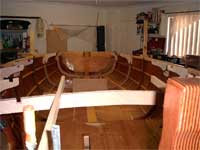
 |
I kept
the companionway opening high enough so
that with one wash board in, the top was
above the cockpit seats to avoid water
getting into the cabin. |
|
While all this was going on I was thinking about
lighting, so I started researching other boats using
LED’s. I played around with it a bit until I
was happy. What I’ve ended up with is the only
incandesent bulb on the boat is in a torch. I have
two banks of cabin lights, one white and one red.
The whites use clusters of 4x10,000 mcd and the red
uses 5x 9000 mcd. These are two way switchable red
to white and side to side.( port to starboard ) I’ve
put lighting in the anchor well, cockpit locker, bunk
lights, deck lights I even changed all the festoons
in the nav lights to strips with 4 x whites. While
I was at it, I also replaced all the instrument bulbs
with LED’s. I’ve reduced the wire size
on lighting and with every light on it draws less
than the cd, so I can reduce battery size.
Every connection is soldered so I have no worries.
I bought them from “Goodwillsales UK”
on ebay, ( continually advertised under electronics),
or for more info on this have a look at THIS.
It includes wiring diagrams. Because
it was so easy to do I’ve ended up getting more
from them and when I first told them what I was using
them for they included a wiring diagram, and all the
diodes. It’s a different light, very clean almost
to an icy bright colour and I have no shortage of
light. None of this trying to read under yellowish
light saving power. It won’t be long before
there won’t be bulbs, just look at the auto
trade, or traffic lights. The other good part is,
all installed, it was under $200.00, but I did make
my own simple light fittings.
For the wiring I drew an outline of the boat and
marked everything requiring power, its placement including
aerials, and spares. Then I mounted split tube and
fed strings through it so I could pull cables back
and forth, pull one through, pull four back, etc,
until I had everything ticked off. These were tagged
and labelled both ends, and the diagram stays in the
chart draw.
Make up an LED lead lamp to try, add more until
you get the light you want. I didn’t think I
could do it, but it really wasn’t that hard.
Next I’ll cover the finishing the keel ballast,
fitting windows, mast tabernacle and painting. I’ll
certainly be needing some serious weekends of Ariniar.
See Craig's website at:
https://arinar.bravehost.com/

|