The idea
In mid-March 2006, I came up with the idea for my
new project, but at first it was only going to be
a model boat, not a full size one! It was to be based
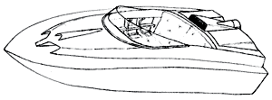
loosely on the lines of a Lesro Javelin (Photo 1),
a model that has been around for many years and still
looks good. I was going to do my own version of it,
using one side-on photo that I scanned from an advert
and the length and beam measurement from the specifications.
It was going to be 38-1/2 by 11 inches with all other
dimensions worked out roughly from the photo.
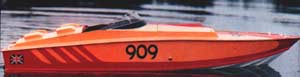 |
Photo 1 |
I didn't know draught or hull shape below the water
and I was just starting to work on this area when
my friend suggested doing one to sit in! He offered
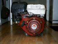
temporary use of a Honda 8 HP generator engine if
I wanted to build a full size one (Photo 2). After
a bit of computer magic on Photoshop, I ended up with
a photo of my head on the model at the scale I would
have to make it for me to fit inside, this resulted
in a 9ft boat roughly 32 inch beam. It looked good
(Photo 3).
| Photo 2 |
|
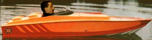 |
Photo 3 |
The main problem with my idea appeared when I managed
to track down a different photo of the Lesro Javelin,
stuck my head on it and it looked a bit too narrow
beam for where the centre of gravity was going to
be with me and the engine in it (Photo 4). My friend
appeared at this time and said: "I thought you
were doing it for two people,anyway" This is
where the boat started to diverge from the Javelin.
| Photo 4 |
|
After some measuring and mock ups with bits of ply
to simulate widths required for seating, I worked
out that I could fit two people and keep the deck/cockpit
side proportions if I made it 46 inches wide. I was
still keeping to the 9 foot length as I had a mock-up
photo of it already. I priced 10 ft sheets and decided
to cut £200 off my boat! I changed the length
to 7 foot four to get the sides from an 8 ft sheet
of ply. This adjustment required another Photoshop
job, shortening the length, but keeping the height
resulted in something that looked possible at reasonable
cost (Photo 5).
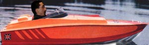 |
Photo 5 |
The plan
The plan started life on Photoshop (again). Using
the side photo, cropped to length of the boat, I resized
the image to make a 22 inch (1/4 scale) photo which
I printed on three sheets and taped together. I still
didn't know any of the 'underwater' measurements,
so I took my first try at weight estimation to see
what sort of volume I would need below the waterline
and came up with 8 inch deep 'V', which was marked
onto the photo and the missing curve added to meet
the bow. I traced the photo and started adding details
until I had enough information to work out bulkheads
etc.
At this stage I joined 6 bits of card and started
on my full-size drawing, using the same type of slotted
together construction as my micro
yacht used. I decided to use 3 laminations
of 3/4 ply for the backbone (I don't know if that's
correct term!) with a mixture of 3/4 and 1/2 ply bulkheads.
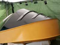
My steering was to be based on a gearbox from a dead
angle grinder, so suitable mounting was designed in
by using two ply braces spaced the width of the gearbox
apart and extending forwards to form the centre piece
between the dummy vents, which were going to be used
for ventilation but ended up mainly for looks. I may
try lights in them. I think the vents look better
than the flat panel that the Javelin has. The braces,
bulkheads and backbone are all slotted to key into
each other, making it hard to go out of alignment.
With most of my plan decided and drawn on the giant
carboard, I started to cut bits of ply. I must say
at this point, that the planning stage keeps going
until the boat is finished; particularly the order
of building. It is easy to get carried away and make
things difficult for yourself, like gluing on the
bulkheads before you have drilled the holes for the
steering and throttle, still possible, but not as
easy or neat as it could have been. Yes, I did that!
There were a few small things that could have went
pear shaped, I was routing a part and the cutter bearing
collapsed, allowing the cutter to decide it's own
path through my nearly finished bit of wood, luckily
it is an 'out of sight' piece, so I left it as a 'feature'!
Another close call came when I was cutting out the
transom, the ply I was using was actually swapped
for a model plane airframe. The friend I got the wood
from had drawn parts for his own version of the yacht
I built, but gave up. The problem happened when I
started following his line with the jigsaw! I realised
within 1/4 inch so it was not a disaster.
The dry build
Starting with the backbone centre lamination, I
then cut my master bulkhead which would be used as
a template to router flush all the bulkheads of the
same lower section. There are 5 which are the same
but have the tops trimmed after routing. Then the
template is trimmed to fit in its final position.
I made the other bulkheads with each edge angled to
fit skin curve at that point, to cut down on sanding.
My angles were pretty close, but there was a LOT of
sanding later to get framework pieces ready for eventual
'skinning'. No glue was used at this stage and I was
able to dismantle the parts and put them in my 8x4
shed after I had finished for the day.
I made up more braces to hold the top edges of the
front bulkheads in place and side rails for the rear/midsection
along with the rear portion of the cabin/cockpit sides
which braced the cockpit and engine bay areas together.
I added doublers to the backbone and adjusted the
bulkhead slots to final size and was now able to pick
up the framework, still with no glue! (Photo 6 and
7) I added more bits and worked out cable runs for
steering and throttle etc.
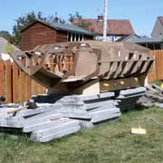
Photo 6 |
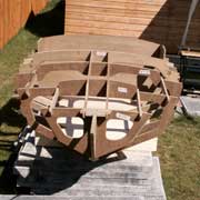
Photo 7
|
Now was the time to think hard about the engine
arrangements! What I had originally planned with 8HP
Honda motor never happened due to my engineering friend
getting busy at work again! I had designed the transom
to take an outboard or an outdrive unit that would
fit over the transom and I even had a lot of the parts
(Subaru cam belt and pulley, chain and sprockets etc),
but no cash to buy the square section steel tube for
the 'leg'.
My neighbour sold me a longshaft Seagull outboard
(non runner) for £40 (Photo 8), which I was
going to use for testing until we eventually made
the outdrive. A night's work had it running and cleaned
up a bit. Repainting the tank finished the restoration.
Next morning, I fired it up to let him hear it. He
looked as if he wished he hadn't sold it!
| Photo 8 |
|
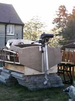
Still keeping my hopes up, I designed the mountings,
throttle and steering to take an inboard motor in
case it ever happens! The transom and engine mounting
plate are laminated ply 2 inches thick and are locked
together with the backbone and bulkheads (Photo 9).
It is very solid and that's before any glue goes near
it. The glue stage was approaching, there wasn't much
more I could do until I glued at least some of my
'kit' together. The trouble was I didn't have a big
enough shed to build it in. A 2.4 metre square gazebo
was fixed to the side of my shed, I added tarpaulin
sides and a portable CD player and I was ready to
glue!
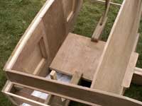 |
Photo 9 |
The Build
I started gluing the bulkheads on one at a time,
using the other bulkheads and braces to hold it until
glue set, then I removed braces etc. and glued in
the next bulkhead and braced it up again. It seems
like a long process, but it ensures that everything
stays where it is supposed to. When all the bulkheads
were fitted, I glued in the braces, added gussets
and ended up with a rigid framework to fit my stringers
(chines?) to. These were steamed using a wallpaper
stripper and a chamber made from 3x3 and a large plank
laid over the top. I clamped them to the boat with
no glue and let them set in that shape. This was not
as effective as I thought it would be, and instead
of a 23 inch curve it sprang back to about 3 inch
curve. I cut notches in the bulkheads to accept the
stringers then glued them in place, added gussets
and could now see some very nice lines appearing on
my frame (Photos 10 and 11).
| Photo 10 |
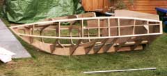
|
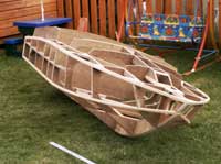 |
Photo 11 |
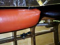
I fitted the deck first, then bottom skins (Photo
12) to give me access through the sides for varnishing
and to the underside of the steering area (Photo 13).
I left the sides off until the last moment, varnishing
all the bits that would be hard to get to later. I
fitted the steering and throttle to make sure it all
worked, then removed it and glued the sides on - sounds
easy.
| Photo 12 |
|
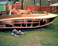 |
Photo 13 |
Glueing the sides on required 2 very late nights
to give me a chance to get the glue onto the frame
and the side clamped on before the glue dried. Mid-day
in summer gives about 4 minutes to get this done.
Clamping was the hardest part as I was running out
of things to clamp to and I did not want to use any
screws (Photo 14 and 15). I eventually managed it
and after trimming off the excess, I could see a solid
version of my idea.
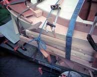
Photo 14 |
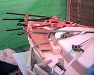
Photo 15
|
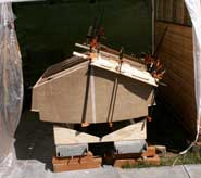
I was worried about water getting on my raw wood,
and the boat had it's own brand new tarpaulin, which
was lucky, as a nights worth of Scottish rain had
broken the peak of the gazebo which filled up like
a pond and was hovering over my boat with about 20
gallons of water straining the fabric and dripping
everywhere. I managed to soak myself but the boat
stayed dry. The poly-shelter was repaired and re-taped
to keep the midgies and moths away from my varnish
and I spent a couple of weeks varnishing!
Varnishing and Painting
This deserves a section to itself as it is a critical
and major part of the build, requiring quite a lot
of time to be spent inside it, upside down with my
legs resting on the back of the seat, while trying
not to sweat on my new varnish! All parts, inside
and out, have at least 4 coats of varnish (Photo 16
and 17). I know a lot of people go for more, but I
was on a limited budget!. I had decided to see how
it looked with just varnish before venturing onto
painting. I had drawn an artists impression of it
(Photo 18), scanned it into the PC and printed off
a bunch to let me colour in a few different schemes,
so I knew roughly what paint scheme I was going to
do if the varnishing didn't look that good.
| Photo 16 |
|
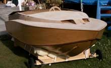 |
Photo 17 |
| Photo 18 |
|
Due to using different woods, glue lines etc, I didn't
like the varnished only look and decided to paint
it yellow using 2 layers undercoat and 5 enamel topcoat
(Photo 19). I was going to do just three topcoats,
but after finishing my first tin of yellow, halfway
through the third coat, I opened my 2nd tin and started
rolling it on, then noticed it was a different shade
of yellow! I had not checked the batch number. I had
to finish that coat and do another 2 coats before
the original shade was hidden. I will check batch
numbers next time! The bottom of the hull got 5 layers
varnish, 2 undercoat and 3 black gloss enamel (Photo
20).
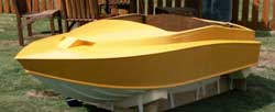 |
Photo 19 |
| Photo 20 |
|
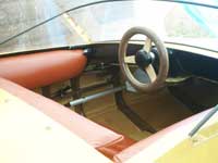
Fittings
Steering is by ropes running around home made ply
pulleys which have mitre saw guides as pulley shafts
and tubing from a baby bouncer as bearings, onto a
drum attached to the angle grinder gearbox (Photo
21), with a laminated ply steering wheel (Photo 22)
which uses a Nescafe coffee jar lid for it's centre
and another to cover the steering bearing (I like
re-cycling)(Photo 23).
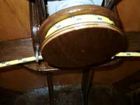 |
Photo 21 |
| Photo 22 |
|
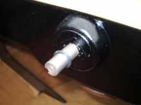 |
Photo 23 |
The tiller arm of the outboard points down into the
area that was going to be the engine bay and has the
steering ropes attatched to the end of it. This led
to the hatch being different to the one in my artists
impression. Throttle is from bicycle gear lever and
cables (Photo 24).
| Photo 24 |
|
I forgot to mention that my daughter's outgrown wooden
bed was used extensively during the build. The head
and footboards supplied large pieces of wood for the
transom, seat back reinforcement, and numerous other
bits. The lower slats from the bed were very useful
for clamping the outer skins to my framework..
There are a total of 198 wooden parts in my boat.
Some parts could have been made in one piece but would
have required more full sheets of ply, which I didn't
have. The windscreen was made from a piece of perspex
that my friend offered me. It is as large as I could
manage from the oddly-shaped bit. The chrome bits
came from a light fitting reflector. Rubber edging
was in deep storage for twenty years before finding
a home! Upholstery was made from a cowskin that someone
gave me years and years ago. All hand stitched by
myself, it was a pleasant break from sanding and varnishing
and has ended up being quite comfy as well!(Photo
25)
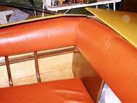 |
Photo 25 |
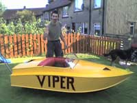
Launching
This is the bit that keeps you going to the end
of the project and it had arrived (Photo 26) about
four months after starting to cut my parts. The boat
was placed on the construction stand that I made from
6x2 timbers and 3/4 ply end plates. The boat and stand
were lifted onto a motorcycle trailer and ratchet
strapped down. During transportation the stand collapsed
a bit and I thought my creation was going to end up
sliding down the road at 50mph! It didn't.
| Photo 26 |
|
We got to Loch Lomond and registered for a year's
use of the Loch for £5! The boat was lifted
into the water, Seagull outboard attatched and I got
in for the maiden voyage. I managed two pulls on the
starter cord before I was blown back towards the beach,
a good push by a friend and I was able to give it
another try and it started! I wasn't exactly skimming
over the waves so I tried full throttle but discovered
that it was at full throttle already. Any thoughts
of calling it a speedboat would have to go on hold
for a while!
I did have fun, but would have liked a bit more
speed.It felt stable in the water and coped with quite
large waves, well, they seemed large from where I
was sitting. I cruised about for about 5 minutes by
myself then went in to pick up my friend. Having the
extra weight aboard did not seem to affect the speed
noticeably, so we ventured out a bit further into
even bigger waves, glad that the dummy vents on the
front were still watertight! The maiden voyage went
without any problems apart from lack of speed(Photo
27).
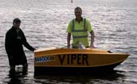 |
Photo 27 |
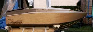
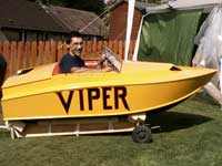
I must say that I enjoyed the entire project (Photos
28 and 29), with varnishing maybe a bit less enjoyable
than sawing and gluing. It has ended up a bit heavier
than my estimate but I reckon it's tough enough to
go through a Jetski! Not easy with a Seagull engine!
That was about to change!!!!
| Photo 28 |
|
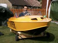 |
Photo 29 |
Someone's Trash
A strange thing happened when I was going to visit
my wife in hospital after a scheduled operation. I
got a phone call from a friend who was dumping rubbish
at the local waste depot. He wanted to know if I wanted
an outboard engine that was being dumped. "What
size", I said, "9.9" came the reply.
I said that I would take it. He said: "do you
want another one that's here, it says 9.9 as well?"
I told him to guard them till I got back from the
hospital and picked them up.
Two Evinrude 9.9 HP, one short shaft (1986) and siezed
solid and the other a longshaft (1983), which turned
over, but had been ripped forcibly from it's mount,putting
a 'Z' bend in the gearchange shaft and wrecking the
casing in a few places. Both were covered, and as
I later found out, filled with what I call seacrust.
I could not see the thermostat when I took the cylinger
head off.
A month or so of cleaning, swapping and painting
parts has brought the motor to the stage it is at
now, about a 50/50 mix of the two motors and requiring
2 seals, a circlip and one mounting bolt. I have just
ordered these parts, but due to having parts of 2
engines, I have to try and explain why I need 3 parts
for an '83 motor and one part for an '86 motor. It
did need rubber mounts but I managed a very good refurbishment
with a scrap of denim and some superglue! Don't laugh,
I saved about £50 by repairing them.
I also need 2 sheared bolts removed, which my engineering
friend assured me he would find time to do! I need
to wait until it is all back together before I find
out if it is going to run. One set of electrics was
corroded very badly. Luckily it was from the siezed
motor. The motor cover was going to be sprayed yellow,
but I decided to cover it with heatshrink covering
for model aircraft, using a surface primer to etch
the plastic before carefully ironing it on. I must
admit that I have built and covered about 90 planes
with this type of stuff, so I am quite good at it.
It is very easy to end up with a lot of air bubbles
or creases.
I then cut the Evinrude lettering from black Fablon.
I think it looks pretty good compared to how it looked
when I got it (them). The photos don't really show
how bad they were. Before (Photo 30 and 31) and after
(Photos 32 and 33).
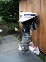
Photo 30 |
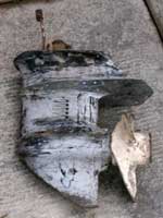
Photo 31
|
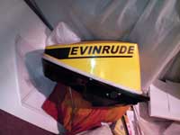
Photo 32 |
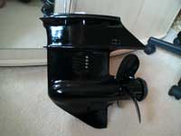
Photo 33
|
I mounted the empty casing on the boat for the photo
(Photo 34) but I will have to wait for my spares before
I can go further. I still have to make up a bracket
for my steering to attach to and fit my throttle cable
to the carb, but I will probably leave these jobs
until I hear it running. Hopefully it will run and
my 'boat' will become a Speedboat. I haven't seen
many boats of this size, so I don't know what to expect
from 9.9HP. I was a bit worried about 'copying' the
Javelin, but I think there are enough differences
to call it my own design ,it is shorter, wider, has
nice vents, different windscreen, is outboard powered
and most of all, it's full size and a two seater!
Hope you like it. Andy. PS. You can never have too
many clamps!
| Photo 34 |
|

|