| To
Part Two
Last time we looked at my first real boat design,
and a little bit about how it evolved from the Michalak AF4B.
Let’s take a closer look at the latter.
Measuring hulls and drawing them is every bit as much of a time-consuming
pain in the butt as it sounds like. But I found the need to do
just that when I realized I’d sufficiently bastardized the
AF4B to give it its own name. While the time commitment is rather
large, the tools are simple and cheap. Mostly string, a tape measure
and some squares. A helper is a wonderful thing for this job.
Chapelle and others have already covered this topic in great
detail, but here I am focusing on a simplified version. Many fewer
steps are needed to measure a nail & glue “Instant Boat”
with a constant chine bevel.
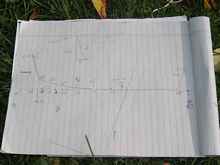
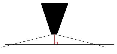
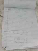
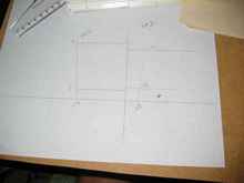
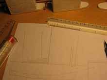
First let’s make a sketch of the side view with bulkheads
and stem. This is not to scale, but it does establish the location
of some important measurements.
To add to this, I also measure the distance aft of the stem of
each of these bulkheads. The point of reference at the stem is
the very top forward corner of the plywood planking. Conveniently
these work out to be mostly even multiples of 12 inches. This
makes sense because these measurements are holdovers from the
original Michalak design, and he tries to stick with round numbers.
Base Lines
Now we need to get heights and a few more lengths filled in.
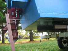
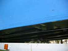
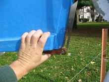
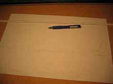
To do this we must establish a reference line at the keel. In
my case the trailer got in the way of running a line right under
the center skid, so I had to run two separate lines 19”
outside this line. Note how I used masking tape to make visible
markings on the hull.
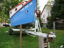
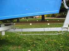
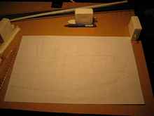
After driving stakes into the ground it takes some jockeying
to get the lines in place. First, they have to match up to marks
19” from the centerline fore and aft. Then they also need
to just touch the bottom of the transom, and run straight forward
not following the contour of the bottom. This assumes a planning
hull with a flat run aft. For a sailing hull, the stern will sweep
up, so the strings won’t touch it. There you will probably
want to try to keep the baseline about parallel to the load waterline.
This is fiddly work in either case.
Now that we’re cold and damp anyway, we may as well get
some measurements.
Baseline Measurements
I started at the stern, since it’s easiest in this case.
A square tells us how far the transom top is aft of the transom
bottom. In this case the string and the bottom are in the same
plane, but for a sailboat hull the square would have to meet the
string. It is convenient to fill in the transom height at the
same time. I also captured the position of the rubrail at the
transom, as it is a continuation of the forward sheer.
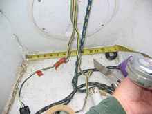
With a simple planing hull I get a break here, as the bottom
is dead flat for about six feet. I don’t need another measurement
until the string departs from the bottom. There I make measurements
every foot—aligned with the bulkheads above—and record
the height.
It is handy to mark the string with masking tape at these one-foot
divisions.
Be sure to measure square to the string fore and aft, and square
to the bottom athwartships. This is very tedious and takes a steady
hand. I couldn’t even get a picture of it. You’ll
want two small squares and a ruler cut off right at the zero mark.
This gets harder when the string emerge from under the bottom.
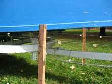
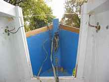
Now we need to connect the one-foot markings on both strings with
a crossing string. More tedious positioning.
Now the measurements are harder to square up. Ideally you need
a square aligned with the transverse line, then its vertical part
aligned with another square touching both the transverse and longitudinal
strings. This is impossible without at least one helper or a lot
of duct tape. Fortunately eyeballing it is close enough for short
distances, if you’re careful.
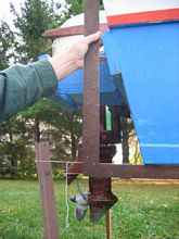
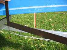
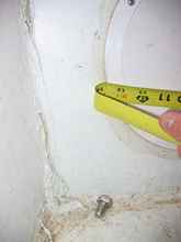
Sometimes you can’t get a direct measurement because something
is in the way. The winch post, for example, block direct measurement
of the stem height. Here Pythagoreas can help. Measure the distance
from the longitudinal string to the top front corner of the planking,
making sure the tape is square with the string. This measurement
is the hypotenuse of a right triangle, and the bottom side is
the offset of the longitudinal string from the centerline is minus
the stem half breadth. The square of the hypotenuse minus the
square of the other figure equals the square of the height.
I also took a bevel gauge measurement of the bow angle as a cross
check. Just be aware that this is more prone to inaccuracy, since
you can easily be measuring a local unfairness rather than the
overall angle. I don’t trust these measurements a lot, but
if any are very far off I do some re-measuring to figure out which
measurement was in error.
Finally, remember to deduct the thickness of the bottom from
all of these measurements. This includes any skids your baselines
are outside of. Enough of this rolling around on the ground. Time
to get in the boat.
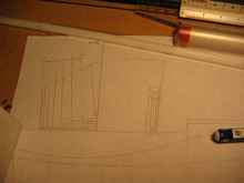
Inside Dimensions
Here’s the easy part. On a fresh sheet of paper sketch
the bulkheads and start filling in measurements. Sometimes this
is easier than others. Occasionally we need to estimate the measurement
to a corner when an epoxy fillet obscures the actual corner. I
put these estimates in brackets so I know it wasn’t exact.
This can be a real problem, actually. Sometimes it is easier
to get cleaner measurements at stations not near a bulkhead, as
there is often less of a fillet obscuring the measurement. On
the other hand these measurements are more prone to error from
the hull being twisted or hogged while the bottom is getting nailed
on. The bulkheads are more reliable, assuming the building cut
them correctly, because they force the hull into a predetermined
width.
There is a way around this doubt. We can get around the fillet
and project the actual measurement. But first we need to measure
some heights.
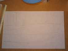
Heights can be interesting too, though more precise. Since most
cabintops are cambered or otherwise peaked, it is often best to
run a string from deckline to deckline, then measure to that.
Make sure to measure square to the bottom.
As you probably noticed, the string here is not at the deckline
at the wales. This one was at the hatch opening.
You will probably measure the width along that same string, but
if you measure outside the cabin, remember to deduct the thickness
of the sides and cabintop frames. The same goes for exterior width
measurements on the transom. If you have fillets at the cabintop
the same trick can work upside down.
Here is the resulting sheet.
Let’s get back to our fillet problem. You might very well
find a cleaner bulkhead-to-side joint a few inches above the bottom.
If so, mark the bulkhead at that height on both sides.
Measure the width at that height and write down both width and
height. In this case I had to go 7.5” high to avoid the
fillet on the forward bulkhead, and the width was 15.75”
at that height. For the rear bulkhead it was 6 and 55.5”.
Actually, getting accurate inside measurements can be a trick
even when there is no fillet at all. I did this mostly with a
tape measure, but it is not very accurate because you have to
bend the tape and guess where it would have ended if it were straight.
A better way is to use a piece of wire or non-stretching twine.
Tape it in place, mark it, then measure between marks. Better
yet is to use two straight wooden sticks. 1x2s or yardsticks work
well with a point at each end. Overlap the sticks so you have
a point in each of the corners you want to measure between. Make
sure your sticks are in line and mark the overlap point. Remove
the sticks and clamp them together lined up at this line. Then
it is easy to get an accurate exterior measurement of the stick
with a tape measure.
This is accurate enough that I have managed to set the tie rods
on my car within tolerance (checked by my mechanic on the laser
jig he uses).
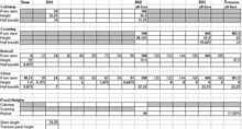
In any case, we will want to put these starting measurement on
an offsets table.
To the drawing board.
Drafting
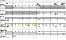
The first thing to do is create a table of offsets. Basically
what we are trying to do is fill in all the values in this table.
I put in bold the values I actually measured from the hull. Regular
type I use for values I generate through drafting.
The very first thing to do is finish figuring out those chine
half breadths where our fillets were causing trouble. This is
easy, and a good warm-up for the real drafting and gets you used
to accurately using the drafting triangles. We’re going
to draw half of a simplified bulkhead. Start with a baseline and
a vertical centerline—I draw two or more of these on the
same perpendicular. Then with the scale rule add horizontal lines
at the height of the sheer (or cabintop) width, and the “fillet
avoidance measurement” we made.
Then fill in the two half breadths (remember to divide your actual
measurements in half!) on the appropriate heights, and connect
them with a line. Where this line intersects the baseline, measure
the real chine width for that bulkhead. Put this in the bottom
half-breadth blank for that bulkhead on the offsets table.
Now onto real drafting.
Michalak covers all you need to know in his wonderful online
series on designing hulls. Regrettably, this is not in his book.
(It is to be hoped that there will eventually be a sequel containing
more on drafting. No pressure, Jim.) I’m using the same
techniques, but more or less as a way of checking the offsets.
Filling in what we know, we can draw a baseline and verticals
for bulkheads, transom and stem. On these we can mark the measured
heights above the baseline and half breadths below. Note that
in my case the bottom height measurements do not line up with
stations or bulkheads. That’s OK.
Then our friend the spline shows us how easy it is (or isn’t)
to connect these points. If you find yourself needing to reverse
the curve or put wavers in it, check for errors. Also remember
that you are measuring an imperfect hull, so you will need to
decide whether your purpose is to document the exact shape as
it exists, or to document your guess at the designer’s intent.
My purpose is the latter in this case, or I would have taken many
more measurements.
If the unsplinable curved persist on closer examination, you
will have to start guessing at which measurements you trust more.
I tend to trust a measurement at a bulkhead, since it is harder
to squeeze the sides in or bow them out during assembly. Fillets
can be a problem, but we discussed that above. A bulkhead can
also be crooked, say if its line on one of the side panels is
an inch off. It happens. Measure from the stem to both sides of
the top of the bulkhead – they should be the same. With
a crooked bulkhead all bets are off, as the hull will be a bit
narrower at that station, and this will probably induce twist
as well. Also be aware that “hard spots” introduced
by butt blocks can affect the fairness of the curves in the plywood.
The closer a measurement is to a butt block the more suspicious
I get, unless there’s a nearby bulkhead to pull things into
line.
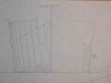
In any case, here is what the spline tells us about the bottom.
Looks reasonable. Next we start a section view and draw what
we know about the bottom on it. Now let’s fill in the bulkheads
we know for sure in these views. Now we have enough to spline
those lines. Take note that we needed to draw the section view
to figure out the actual half breadths of the rubrail, since we
measured the bulkhead widths at the coaming or cabintop.
Now we can add station lines.
Now we have all points fully defined. So let’s transfer
this information to the section view. First the bottom.
Then the rest.
Well, this can’t be right, can it? All of the section
lines on the sides should be parallel, otherwise there is twist.
Nail and glue “Instant Boat” hulls can’t have
side twist, or you wouldn’t be able to rip the chines to
a constant angle. Well, have a look at station #1. We have twist
in the bow, and I’m pretty sure the actually hull doesn’t.
Furthermore, Michalak designs all outboard-powered boats with
a 15-degree transom rake, and this doesn’t measure 15 degrees.
Let’s figure out where I went wrong.
Adjustments
Well, the transom adjustment was simple. I just plain measured
wrong! I didn’t have the square firmly against the bottom
for its whole length. This changed the fore and aft distance between
the bottom and top of transom from 4” to 5.25”. This
in turn made the transom angle way closer to the intended 15 degrees.
Still one degree off, but probably close enough for any motor
to work fine. I bet Jim drew it at 15 degrees, since he says he
always does for powerboats, and it wouldn’t take much error
to end up with 14.
The bow was nearly as simple. I had not taken into account the
width of the stempost. My splined lines should not have crossed
the centerline at the stempost, but rather ended a touch under
1” from it. This straightened out the bow, and now we have
this.
About this time you start wondering how it can possibly be that
you’re not done yet, and realize what an impressive achievement
it is that Michalak has drawn over 100 boats. Drawing one is an
awful lot of work—about like recording an album. But how
many artists record 100 albums? Even if he’s four time as
good at it as I am, how many artists record 25 albums?! Impressive.
OK, back to the drawing board.
Notes on Drafting
I should mention something about these splined lines. My rather
extreme sheer causes some quirks with the spline. The sheer flattens
out forward—almost a “powderhorn” sheer, but
not quite. This means you need four or five spine weights, where
Michalak’s easier lines normally need only three or maybe
four. But still this line goes into place without too much coaxing,
and so it is on the full-sized boat.
Aft is even stranger. The upturned stern makes the rubrail line
reverse its curve in the plan view. It is still splineable, but
you need at least four weights and they had better be heavy. Even
then the spline tries to shove them out of place. This accurately
reflects that it will be difficult to shove that piece into place,
which is why I had to laminate it.
If you think about taking on a hull that isn't nail and glue
Instant Boat construction, remember that you don’t have
these handy cross-checks available. Knowledge of the rules used
to design the hull is the only reason we could isolate some of
these errors. Far more care is required for measuring a hull designed
with fewer constraints (e.g. fiberglass or carvel planking).
Drafting limitations
The beauty of drafting is that it is a relatively quick and easy
way to fill in the unknowns in the offsets table we are building.
The trade-off is in accuracy. I am making these drawings at a
relatively large 1/12 scale using a 0.5 mm pencil. Assuming a
pencil mark of the same size, my markings translate to a little
under 1/4” wide when blown up to full size.
Practically you can do a little better than this by using magnification
and estimating the center of the line, but you can see why offsets
tables made from full-size lofting are much to be preferred! You
can also see why guys like Bolger would sharpen their pencils
on fine sandpaper and make marks that a lot of us can’t
even see when working at ridiculous scales like 1/64. The best
I can do is 1/16 before the errors start getting way out of hand.
However even when drafting by hand we can still use computers
to fix some of this error. We’ll dig into that next month.
Rob Rohde-Szudy
Mazomanie, Wisconsin, USA
robrohdeszudy@yahoo.com
*****

|