 Custom Search
|
|
| sails |
| plans |
| epoxy |
| rope/line |
| hardware |
| canoe/Kayak |
| sailmaking |
| materials |
| models |
| media |
| tools |
| gear |
 |
 |
| join |
| home |
| indexes |
| classifieds |
| calendar |
| archives |
| about |
| links |
| Join Duckworks Get free newsletter Comment on articles CLICK HERE |
|
|
| Make and Make Do |
By Rob
Rohde-Szudy - Madison, Wisconsin - USA Improving the Bolger Light Schooner Motor Well (Again) |
 click for bio |
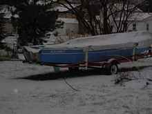
Greetings, all! I’m glad to be back to posting on Duckworks! A perfect storm of weather, job changes and musical instrument projects that couldn’t wait forced me to put boat stuff on the back burner for a while.
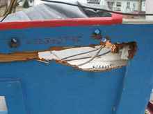
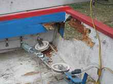
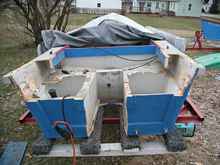
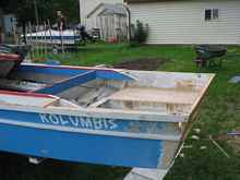
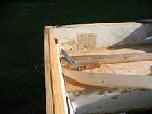
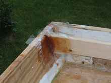
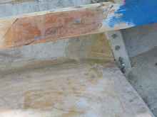
During this period of neglect (and before, actually), the light schooner’s transom got a bit soft in spots. Here it is after I picked at it a bit with a knife.
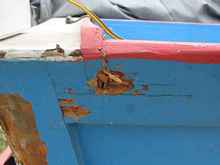
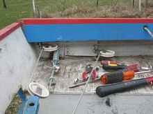
I guess it is time to do something about it. This will also allow an experiment with the motor well. If you recall from prior articles, the trouble with the light schooner’s motorwell is that leaving it open creates a small geyser under sail, and any kind of cover is a pain to fuss with. Bob Guess wrote me with a solution. On his light schooner, he left the well open and added an opening at the bottom of the transom. This lets the water escape astern before it becomes a geyser. That sounds well worth a try! Let’s take out that rot. Cutting out rot First thing is first, however – photos of the steering arrangement so I can remember how it goes back together!
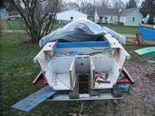
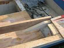
I wasn’t sure how much cutting I’d end up doing, so I did it one stage at a time.
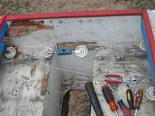
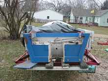
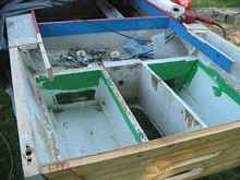
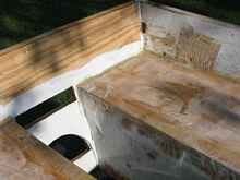
I decided to take out the motor well decks, since they were pretty checked, and I figured I could get rid of the deck plates if I connected these air boxes to my air box under the slop well.
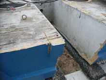
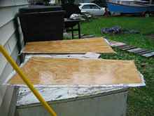
Clearly it will be easier to make a whole new transom.
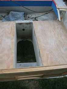
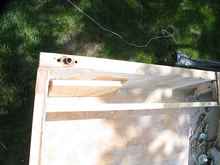
This looks like short work in the photos above, but it really did entail a lot of quality time with the Saw-Zall and even more with hammer and chisel. New transom Making the new transom isn’t much harder than making the original transom, except that we need to add another hole in it. First let’s plot it out on the plywood – a clamp is handy for a third hand. Then let’s transfer the opening for the tiller from the old transom, since this was my own addition and not on the plans. Test fitting is a good idea. There is usually some adjustment to be made. That’s better. At the same time, we should mark where the motor well sides intersect the transom. These markings guide where we put the cutout. Here it is with the cutout done and the framing sticks in place. I ran the lower framing stick across the opening because that is where the rudder hardware attaches. I think it will still be enough of a hole to let the water out. Here it is fastened in place. I used P-400 and stainless screws and nails. Note that I pre-painted the parts inside the compartment.The green paint was left over from the Polepunt project, and it seemed like a good place to use a mismatched color, since I won’t be looking at. At the same time I also cut, epoxy coated and painted the holes that ventilate the compartment to the compartment under the slop well.
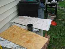
Since my hatches on the slop well bulkhead aren’t especially watertight, I should really fill these compartments with empty plastic soda bottles. I can do that later from the front. New motor well decks This time I’m glassing the decks to avoid checking. I did this with polyester resin because I’m cheap and it works better than you’d think, especially for something flat and horizontal!
I first painted on some plain resin thinned with acetone and let it soak into the wood. Then I used an old credit card to squeegee on a thin layer of plain resin, and set the glass fabric in it. Finally, I catalyzed some resin with a bit more catalyst than normal, mixed, and squeegee’d it into the fabric fast. It is good to do this on a cool day to avoid the resin catalyzing before you can squeegee it.
After a bit of sanding and painting the underside, they are ready to go.
And here they are with the fiberglass curing on the edge grain.
Carlins and side decks AS you noticed above, I had to cut away some of the deck carlins due to rot. I think part of the problem here is that Bolger’s design leaves some of the carlin’s end grain exposed where it notches into the transom framing. I’m updating this construction by stitching and taping the joints. But first we need to fit them. Our friend the bevel gauge tells us how to cut the aft end.
And we simply trace the forward end from the existing carlin.
Here I have dry fitted the new pieces of carlin with two screws fore and two screws aft for each. The screws through the transom act more like pins to keep the carlin in place while taping the seams. I used stainless so I don’t need to mess with removing them. Then we epoxy the forward joints and then fillet and tape the aft joints in the conventional way.
Note that I used packing tape over these joints. This allows me to make a tidy job of final shaping on the fillets with a finger. Be sure to come back after a while and do this again as the epoxy starts to stiffen. (Or be smart and use Bondo, which cures hard much faster.) By the way, credit for this “poor man’s vacuum bagging” idea goes to Gary Blankenship, though I seem to remember Steve Lewis from Iowa mentioned something similar to me at a messabout ages ago. I seem to remember someone else had an article with pictures too, so there’s lots of folks who deserve credit on that one. You know what? It works! I have always hated taped seam construction because of the unmanageable mess and huge amount of sanding. I think I might be starting to come around with packing tape as my helper. However I learned a few important things:
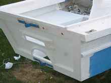
(Thanks to fellow Wisconsinite and Duckworks writer Tom Pamperin for the cool numbered-list-of-humorous-lessons-learned format. I’ll see if I can ruin it for everyone…) Before adding the side decks, I added some 1x lumber to the sides to provide a place to bolt down the padeyes that hold the steering pulleys.
And we also need to get rid of a blind corner that will hold water, just aft of the frames extending up from the bulkhead the motor is clamped to. I did this with a couple triangles of scrap plywood, a couple long deck screws and a lot of PL400.
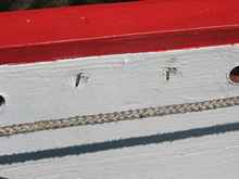
Moisture control There are still a few important details to be filled in. I think one of the major points where rot started was the rope holes where my stern ladder attached. This time I epoxied scraps of ½” copper pipe into those holes. This should create a watertight seal. I did the same with the rear “oarlock” holes where the light bar bolts on.
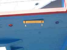
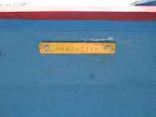
Hull number Speaking of copper, I realized I obliterated the hull number when I removed the old transom. Since I have a set of number punches, I made a copper number plate and clench nailed it to the hull.
So does it work? Well, I’d love to tell you, but another thing I’ve learned from this boat is that there a limited number of days in the year in the Midwest when it is nice enough to go sailing at the same time as being able to make time to go sailing. I guess the final testing will wait for spring. Until then we’ll just have to trust Mr. Guess. |