| Send
items to chuck.leinweber@gmail.com
for inclusion here next month.
The Treasure Chest is a place to put those cool sailing,
cruising, motoring, boatbuilding or boating tips you have. Send
us your ideas...
This time we have...
BoatCalc
There's a nifty little Java program by Peter Vanderwaart, moderator of the Yahoo boatdesign forum, that does lots of stuff, but will calculate sail areas and CoE from edge dimensions. It's called BoatCalc and can be obtained from the Files section on that group.
Ray
https://slidercat.com/blog/wordpress/
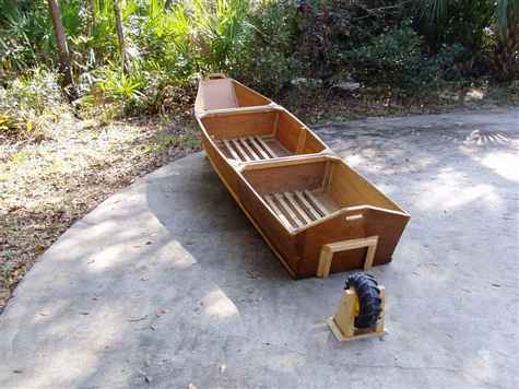
Fred's Wheel
I found a ten inch diameter plastic wheel from a big wheel and could not resist hooking on a boat. I have my detachable wheel hung on the transom of Ruby. It seems to work well, easy on and easy off - up and down the driveway so far, next to the park and down the kayak trail.
Fred Night
PDR Tiller Extension
... you should sit where the boat is so balanced as to float with both bow and
transom out of the water. I found that often I prefer to sit in the back or on the side, like when I just roam about or have a guest in the boat. For this I made my tiller-rudder combination. I have posted it long ago and don't know if you have seen it.
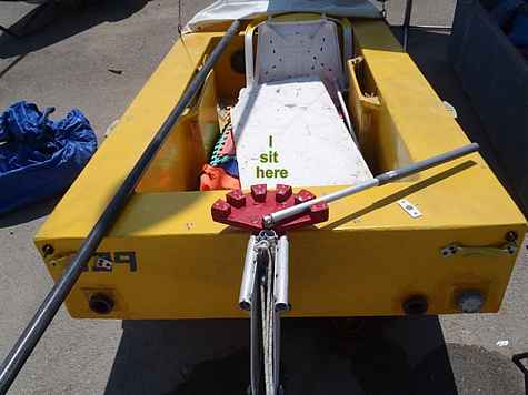
Gil
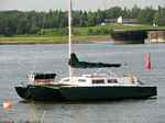
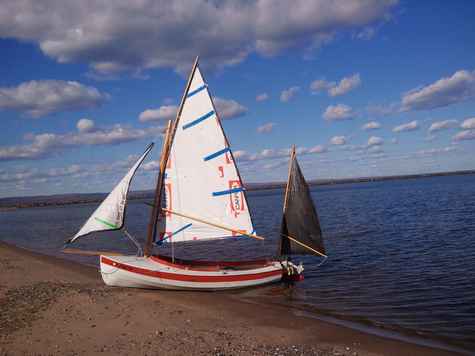
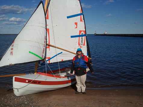
Cheap Sails
Someone recently commented on the sails for my Welsford Navigator. They said something like, “cool sails….kinda industrial sheik”. My response was…”are you talking about that $35 set of sails I made??? : )
Who would have thought that I would have sailed 2 summers on so little money and just a bit of time.
This was a fun project, driven by a lack of money and a desire to go sailing! I had looked at several sail options for my Navigator, including having the good folks at Duckworks make a set for me (about $800 if I remember right), putting together a Sailrite kit (about $550) or making a Polytarp sail a la Dave Gray's web site (hope you don't mind Dave!). Dave does a good job of laying out the process of cutting the sails and offers some hints about putting them together.
Somewhere in all this fooling around, I decided to simply do it myself! The key questions I had were about how to get a reasonable shape to the sails, in terms of building in draft and placing the draft in the right place. Dave and other sources talk about building in draft by using edge curves, rather than cutting straight edge lines, and by using darts, or folds in the material. That sounded doable for me.
So…how to figure out what "proper" draft and "edge curve" actually means for my standing lug rig, sprit boom main, jib and mizzen. It turns out that there is not a lot of information about this process just laying about. I remember asking someone from the group for help and got the following response:
" The point of maximum draft is often placed from 30-40% aft of the luff. This too, can vary, depending on rig design. Put it high enough to look right, but, too high, you'll lose effective area since the camber flattens out below the point of maximum draft. Don't forget to add edge curves. The luff on a lugsail can be slightly concave (curved inward) to help it set tightly. The head should have a bit of convex shape to offset yard flexing. The foot should be cut dead straight."
SO....that gave me a start, but some of this ended up being "what looks right!
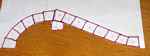
The "tool" I used was a spreadsheet that Thomas Hamernik put together, called "SailDart" (search for “saildart” on the Duckworks site to find this). This is a spreadsheet that has formulas built in to calculate the material you need to cut, taking into account the material needed for any darts you are using to build in your draft. Besides giving you the lengths and angles you need, it gives you a visual of the sails, based on your inputs, so you can “see” what you are trying to do. It took a little bit of playing around, but worked well! (thanks Thomas!!) I did have to convert the sailplan measurements from metric to standard (or visa versa) as the spreadsheet is in english standard.
For material, I ended up using Lumber wrap material. This is the stuff that you see wrapped around pallets of lumber being shipped by train, truck..etc.... It is a woven laminated material, lightweight, tough and not nearly as crinkly as tyvek (which means it's not LOUD in the wind). It appears that different companies make this different ways. I went down to the local lumber store and told them what I was doing and asked if there were any extra sheets of this laying around. They helped me out by pulling some of the nicer sheets that had come off of lumber and they were saving to reuse...else I could have pulled what I wanted to out of their dumpster. This material has worked great..tough and hasn't stretched in a year and a half of sailing.
I cut the sail on the floor of our church fellowship hall...nice big flat surface!
Tools and materials I used included: weights for holding flat, marker, measuring tape, scissors, 100' poly rope 3/16", 3" vinyl tape (tarp tape)100', double back carpet tape 3" - 100', 3/8" grommets and 7/16" grommets....rubber mallet (most tape companies suggest you use a mallet to help bond the tape to the material you are taping).
I think that was about it! (Check Dave's site for more details or just buy a kit from him with all the materials you need!)
Couple more notes. I did tear out the clew corner the first season because I didn't take enough care to sufficiently reinforce it. Sailrite sells plastic "jiffy head boards" which I added to the corners. They were easy to install and have worked great. They're only a few bucks a set. I also learned that you really do need battens for the main and mizzen of this sail to keep the roach from excessive flapping about. I made the batten pockets with vinyl tape over a strip of the wrap material (ie:cut a strip of wrap material a little bigger then batten width, then taped that down on the sail to create a pocket, overlapping 3 strips of tape. Again, I’ve been surprised at how well those have held up. I used strips of Alaskan Yellow cedar for battens initially...then found some used fiberglass battens.
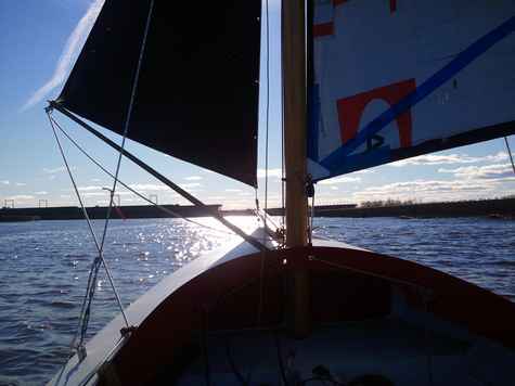
The sails do seem to work quite well, though I still question if they are quite as efficient as professionally made sails. I do plan on buying a real set..some day...I think : ).
Tim Ingersoll
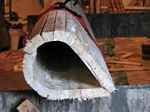
Building a Mast by a Strip Composite Method - It broke!
My 4” x 6” x 32’ mast snapped in the middle while transporting my 26’ Norman Cross design trimaran to its resting place for the 2009-10 winter.
The broken mast had replaced an earlier one that I was told rotted at the spreader—probably due to inadequate protection when the bolts were inserted. The more recent broken mast consisted of two 2” x 6” (spruce?) boards epoxied together with a small centre slot to allow internal wiring. It was covered with a thin outside layer of fibreglass, but the strength was in the wood. The recent break happened when the lowered (horizontal) mast began bouncing while the boat was going over potholes. The A-frame supporting at the middle of the mast collapsed and the mast dropped about 4’ onto the stern structure, snapping it neatly in half. The two pieces with the rigging were hauled up on deck and the trip home was completed. (The loss of a wheel bearing on that eventful 2-mile trip is another story!)
Build rather than buy
With the entire winter ahead, I remembered a small bit in The Gougeon Brothers on Boat Construction (5th edition, Meade Gougeon, pp 278-9) where they expand their strip canoe section to suggest the same technique can be used to construct hollow masts. Being severely budget-limited, it seemed fascinating. I could get epoxy (from Noah’s—not WEST system because it is not available locally on PEI and I long ago got started using the EAST system 5:1 product that is stocked in the local boat supply shop) and surplus fibreglass (from Defender). I already had lots of lumber cut from trees in our woods, so it looked like a winner.
Requirements
I needed a mast that could hold up to the potholes in the road when supported only at one end and the middle. To avoid a repeat of the previous break, I wanted the new mast to be stronger and lighter—solid did not seem a very efficient of weight. I contacted Gougeon Brothers (of WEST system epoxy fame) but they could not advise on the thickness of the wood strips to use because there was very little data on construction of such relatively long masts. One of their older customer-relations gentlemen (who had sailed with the Gougeons in the early days) kindly did some research and returned with the unofficial advice that thicker wood (than the ¼” mentioned in their book) would be better—perhaps ¾” or even 1” thick. Posting the question on the Duckworks forum brought a wide variety of responses including several which suggested I make it solid (with a lengthy dialogue on where to locate the best tree for the job), or in a birds mouth (hollow) shape, or just buy an aluminium one. A few remembered old masts they thought were made from strips, but none of the replies could supply any hard data—the most relevant advice was that the mast would either gain its strength from the wood or from the fibreglass but not from both due to the different characteristics. Ideally, I was told, I should build a test mast first and destructively determine its characteristics before building the real thing.
The Plan and Form
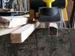
Not allowing myself the luxury of extensive testing, I chose to forge ahead anyway. I settled on a teardrop shape so the mast would produce relatively little forward wind resistance and still have extra front-back stiffness for transport. Since it was expected to end up much lighter in weight, I increased the original 4” x 6” dimensions to 6” wide by 9” front-to-back—a little wider than before but considerably deeper, tapering in at the rear to the sail track. The original plan shows 1” x 1” strips which were eventually tapered so the faces would meet and not require so much epoxy.
I cut pattern boards out of ½”OSB and used wood blocks screwed at about 2’ intervals to a “back” of 2 x 4 s.
I had lots of locally-cut poplar lumber, which is not especially strong, but it is light and clear of knots for long distances. I ripped it into 1 x 1 “strips”, cut out any knots and then scarfed the pieces. The scarfing was done on the same radial-arm saw, giving about 6” of overlap. All the relatively short pieces were epoxied into 32’ long strips “clamped” while the epoxy set by temporary nails.
Half at a time
The completed strips were drywall-screwed onto the edges of the pattern pieces of the form.
To avoid using massive amounts of epoxy filling the gaps, the individual strips were tapered using a power planer.
Rather than epoxying strip-by-strip, I mounted all the strips and trusted the epoxy would get down in the cracks from either the outside or, subsequently, from the inside. After all the strips for one half were fitted and screwed in place I ran epoxy over the outside only between the screws to bond the pieces together.
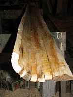
Then the screws were removed and the rest of the outside was glued with epoxy. That first half was removed from the form, turned over, and then had the inside glassed.
The intent was to gain inside protection from moisture and also to have the wood layer sandwiched all around between inside and outside glass. In the end I did not know if the strength would be in the glass layers spaced like a foam-cored fibreglass deck or if the strength would be in the wood with the glass just holding it in column. If it breaks I will be able to report on that! Then a second half was built on the same form. When both were done, one half was reversed top-to-bottom.
Connecting the Halves
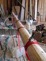
The two halves now made up a teardrop shape, but each half was still floppy. I installed some internal wiring and spacer blocks where the stays would attach, and arranged pulleys for the halyards. The next step was to epoxy the two halves together. After some fitting with the power planer, a liberal supply of nylon ratchet straps clamped the two halves together.
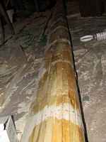
After an initial dry fitting, epoxy was liberally applied to the facing surfaces and kitchen plastic wrap used to keep from gluing the straps to the mast. Once the two halves were firmly set together the mast was much stiffer, but not fully what was hoped.
The final step was to wrap the entire outside in fibreglass. That was a labour intensive job for two people—one mixing the epoxy and the other applying it to the glass. The result was considerably more stiffness—enough to vindicate eliminating the spreaders and using only 4 stays from the top and a pair of side stays from the middle. At this point I bored holes for 1 ¼” dowels which provided mast steps as well as giving extra stiffness by tying the two sides of the hollow mast together along the centre.
Finishing and Pivoting
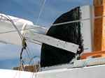
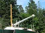
The external sail track was screwed into the back edge. On the top I attached a large radar reflector (that is a previous story). I fitted a rectangular piece of the old mast in the bottom and attached steel plates to allow the mast to pivot at its base. From figure
and
you can get an idea of how the mast is hoisted with a separate temporary pole and a “cum-a-long”. The problem had been that the side stays did not attach at the same height as the mast pivot so extra arrangements had been needed to keep the mast from swinging sideways while being lifted. As part of the overall job I built a 15” radius ¼ circle attached to the deck to keep the two side plates at the base of the mast in line as it is ratcheted up or down.
The Result
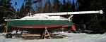
Somehow I forgot to get pictures of the final set-up—we got done so late in the season we only went out once before a passing hurricane convinced me to tow the boat back home. The only photo I have is a shot last week of the mast at rest (under 6” of snow).
This new mast is considerably stiffer than its predecessor and about the same weight. It looks unusually fat for the size of the boat and I wonder if windage will give a problem in severe weather. Still, it has already survived 55 Knot winds and significant waves while moored in a passing hurricane—no trouble other than dragging an anchor and moving the mooring block.
Would I do it again? It turned out to be a very time consuming project and I estimate $250 US for the two gallons of epoxy and the fibreglass. I don’t know what a 32’ aluminium mast might have cost, delivered here on PEI, but I would guess $1000 or more, and that would have required all new fittings. I will probably wonder for the next decade or two if lighter construction might have sufficed, but my goal was to not learn at some point in the future that my chosen design was too light! The biggest down to the build was the fact that the 30’ form wouldn’t fit in the heated basement. Waiting for warm weather (for the epoxy work) delayed the start and the build took so much time the job finished near the end of the season—we barely got any sailing in last (2010) season. Like the cry of some baseball fans I know, “Just wait ‘till next year!”
Tom Schultz
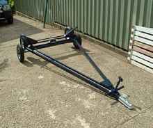
A Trailer for the Welsford 'Truant'
Building a boat in Fiji poses a number of logistical problems, for many of the bits and pieces readily available at your local marine store or chandler are simply not there. As the building progressed I could see that there was no way I would be able to manhandle the boat into and out of the water; a trailer was an absolute necessity. There are boat trailers in Fiji but they are commonly made by welding an old back axle to whatever bits of tube or angle are to hand. This didn't appeal, so on a trip back to UK, my country of origin, I put together a package of the bits that I thought would be unobtainable in the south pacific. These included:
The axle/suspension/road wheel units. These are of the 'Indespension' type, where springing is provided by a rubber bush in torsion The front ball hitch A roller Lighting connectors A towbar for the vehicle that I drive, a 1997 Honda CR-V
The design was dictated by:
- The available materials. Steel rolled hollow section was easily available in two useful sizes, 25 x 25 x 1.6mm thick and 25 x 50 x 1.6mm thick.
- The need to keep the main road-going trailer out of contact with sea water. Hence the piggy-back design. The launching dolly uses relatively cheap wheelbarrow wheels and a loose axle so that if corrosion does become a problem these parts can easily be replaced.
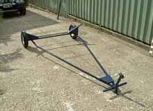
- The position of the Truant's centre of gravity. By rough measurement of the weight of the boat, using bathroom scales first at the bow and then the stern, I found the C of G to be about 245mm forward of Frame #3. The ideal weight distribution for a trailer is to have about 10% of the total weight as downward force at the hitch.
- Most of the weight of the boat to rest on the roller when on the road, with the bunks which are part of the launching dolly acting as stabilizers. I also wanted the roller to be beneath the centre board so as to take its weight when on the road.
- The need to absorb the moments arising from the cantilevered road wheel suspension units. This led to the simple triangular design of the frame.
The final design has the roller about 80mm forward of Frame #3, neatly under the aft end of the centre board and the bunks on the launching dolly almost exactly beneath Frame #3.
Hot-dip galvanizing would be the ideal finish, but I have settled for metal primer and one topcoat! Well, I want to get the boat in the water as soon as possible.
The trailer was largely designed using a CAD package, and the two main drawings are reproduced at the end of this article. I had the advantage that I had previously transferred many of John Welsford's plans to the same CAD format in order to make a scale model of the dinghy before starting cutting for real.
A note on the photographs: These were not all taken on the same date, and not necessarily in the sequence that they are presented here. The eagle-eyed reader may spot on-going improvements.
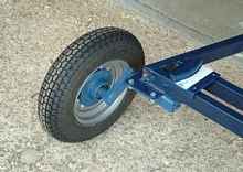
Faintly visible are the three wooden pads that take the weight of the launching dolly. These have been left in white undercoat where they contact the dolly. It would have been better to use a plain round roller rather than the V-shaped one which bears rather heavily on the edges of the two protective strips each side of the centre board slot. I may well change this roller later. Material: the main frame is ex
25x50x1.6mm hollow rectangular mild steel tubing.
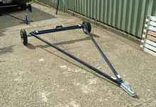
The bunks and the trapezoidal wooden block at the forward end were later padded with carpet. Material: the main frame is ex 25x25x1.6mm square hollow mild steel tubing.
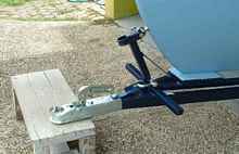
The launching dolly is secured to the boat by a 10mm pin (an old bolt) through the boat's towing eye. The eye is given some protection by being nestled in a shaped wooden block glued into the U- shaped piece at the top of the front post of the dolly. The dolly is in turn secured to the road-going trailer by the shackle visible just above the two handles.
|
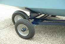
Road Wheel and Suspension |
These are off-the-shelf (but not in Fiji!). The suspension is provided by a rubber bush in torsion. This picture has a clearer view of one of the two aft landing pads for the launching dolly.
The bunks were fitted last, and made to suit the boat.
With a towing ball about 425mm above the ground, the boat sits remarkable level.
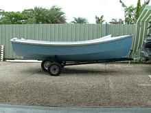
The point at which the launching dolly wheels take over. From here on, when launching, the main weight of the boat is taken by the bunks with a small proportion by the pad at the front of the dolly. When loading back onto the road trailer, the front of the dolly is lowered, whereupon the roller on the road trailer takes the weight while the dolly is slid forward.
Plans FREE
By John Beatty, Nadi, Fiji, South Pacific
The Conversion is Almost Complete
There's a tiny application program that lots of tech people use everyday. It converts anything to anything else. It's a free gift from a guy named Josh Madison. The name of this gem is simply: "Convert".
Go to this URL and look: https://joshmadison.com/convert-for-windows/
It's free, doesn't take up much computer room and runs with every operating system known. I've never heard of it causing a problem. Installing it takes a few seconds and puts a shortcut icon on the screen. It's one of the first things I put on any new computer.
Roger L.
Rot
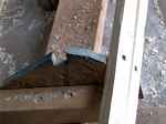
I've just been working on restoring a wooden boat that wasn't well stored and had a lot of rot.
We all came away certain that this did not have to happen.
1. Good ventilation would have prevented it. (a solar cell in the cover and few small fans in the ends would have helped.)
2. spray the interior thoroughly with Boric Acid (cheap from the exterminators supply, and quite safe) every time its out of the water or going to be stored.
Charlie Affel
Sculling Boat
Someone wanted to know how to put a lawn mower engine in a boat. Here you are. It's really easy if you know the secret and have a mechanical genius like Howard to do it.
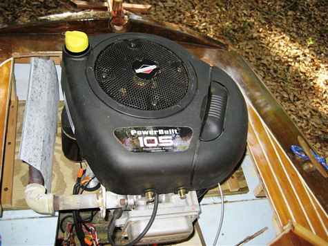
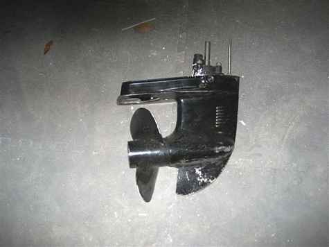
We started with a really slick hull, a 17 foot Whitehall which only takes about two horsepower to push at hull speed. We needed a new vertical shaft motor. The smallest we could find with electric start and generator was this 10.5. Price $300-free shipping from a small engine site in line. And we needed this, a lower unit from an outboard motor. This is the secret. It has forward and reverse gears, thrust bearing, is sealed so you can bolt it to the bottom of the boat and even has a water pump if you want. They are readily available at any outboard shop for free, they usually have a big pile of old ones out back.
Everything else is just mechanical trial and error but pretty straight forward. The two major problems we encountered were not the ones we expected. First, the boat wouldn't slow down. Even at idle we were still fast. We changed props and cut down props and finally got it to slow somewhat except the motor ran too slow and would load up and run rough. This motor is way too big for this boat. Howard finally had to install some reduction pulleys to make it work. The other problem is the exhaust heat. We tried everything we could think of including what you're thinking of right now. The one shown here had a blower to blow the heat out the back but it was still too hot. We finally made a water jacketed muffler with a small pump pulling water from a thru hull up through the muffler and out. We tried using the water pump in the lower unit but it pumped way too much water.
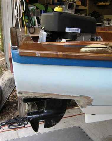
When it's running it looks and sounds like a diesel. You'll need a fuel pump but that's easy, just go to your local mower shop and buy one for about $10. I know, it surprised us also. They work off the vacuum at the carb and the diaphragm pumps the fuel. Our tank is up front along with the battery. If we do this again we'll use a 5hp and not worry about the electric start and a smaller lower unit, this one is from a 30. Howard knew about flexible couplings and such. Good luck.
Dave
Lucas Boatworks and Happy Hour Club
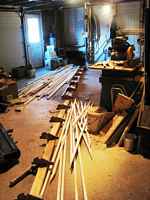
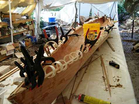
Clamps- this may be a record. Stan's putting a rail on my 20 ft kayak and there are 105 clamps of one kind or another holding it on. If you haven't seen them, these white circles are pvc pipes. They work pretty good for light holding jobs. Paul was here last week and took this one of me out in the shop.
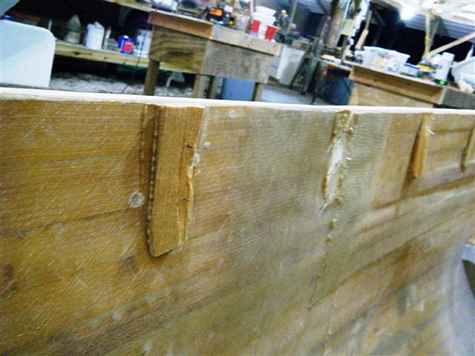
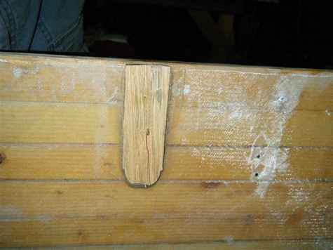
Talk about boys and their toys. Now for a follow up on the PL Premium glue I told you about. This stuff is fantastic!!! I glued these deck supports to the hull with just a line of glue and held with a little brad. I decided to do it a different way so they had to come off. I hit these with a hammer to knock um off. You can see what happened. No glue failures at all. They're rock hard yellow pine and I had to swing really hard. They all broke except the one I hit right up against the hull. That one ripped the 25 ounce glass in half, good thing I have a big grinder. I doubt if I'll ever use epoxy again to fasten things together, this stuff is so simple and a case of 12 only costs about $50. I'm closing up the cockpit of the big launch. Here's some of the stuff in there, lots of wires for the engine, a/c and d/c power, fuel systems for the engine and the generator, blower, battery, air conditioner, all stuffed into a small space. I think/hope that I can get to everything when I need to. Last is a shot of the shop at night.
David Lucas
Thanks to all who contributed this month. We got great ideas sent from far and wide. Put your thinking caps on and come up with those ideas for next month. Mike John
|