|
To Part One
To Part Three
To Part Four
To Part Five
Keeping it Simple
In the first article I explained why I needed a cabin on my John Welsford Pathfinder and how I planned to tackle the task. Now I’m actually getting down to work in making this happen.
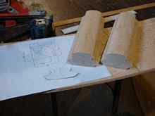
The basic cabin plans were completed (see bottom of page) and it looks to be a fairly simple build, only complicated by my situation mentioned before. From the lines in Johns plans, I developed the side wall curve to match the curvature of the boat and gradually narrow at the front. When the new spray rail is installed it should closely match the curve of the cabin sides. The cabin width at frame #4 is at the edge of the inner deck, the same dimension as on the original plans.
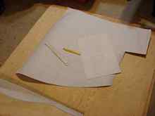
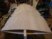
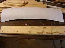
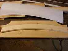
I printed off full size templates of the aft cabin wall sections, forward and side walls and an oversized roof halves.
I find this easier than drawing it onto the plywood and it works for me. The parts were nested onto 2 sheets of 3/8” plywood (I’m sure ¼” is strong enough too) and were cut with the jigsaw.
The side walls were left intentionally long for reasons I’ll describe later.
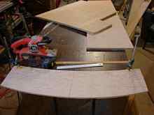
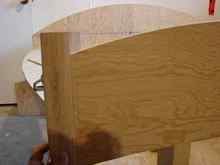
The cabin corners are to be rounded and I arrived at that particular radius simply because it was the largest I could make with the usable hardwood I had. The corner posts were marked and cut using only the table saw with the blade set to one angle, all I needed to cut the opposite 90 degree was to lower the blade.
The last cuts made were the back side 45 degree cut and then the outside 45 degree cut. The outside radius shape was then made with my belt sander clamped to the bench, I'll clean it up more later.
Now all I need is a form to attach this stuff too.
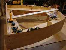
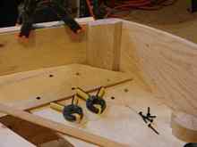
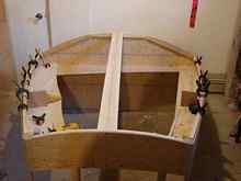
My plan view of the cabin inside the walls was scribed onto pieces of scrap plywood left over from the boat build some 2 years ago. I knew it would have a use some day. Pieces were cut and matched to a template I cut from paper and then was screwed together with drywall screws. (it’s a simple arc so templates are not essential).
The front corners were cut to match the hardwood corners previously cut so the walls follow the form into the notch in the maple.
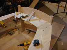
This piece will hold the front and side walls. This step can be ignored if one wanted to make a sharp corner to their cabin and just have a block inside to screw the walls too, or even epoxy glue instead. The two halves of the aft bulkhead were screwed together with a piece of 2x4 at a height somewhere in the middle of the side walls.
This aft bulkhead as it turns out is just a part of the building form and won’t be going on the boat. It’s there to attach the parts too, nothing else. The wall form is then screwed to the top of the 2x4 on the aft bulkhead. A set of braced legs cut at the correct height will keep the aft bulkhead vertical and the side walls horizontal.
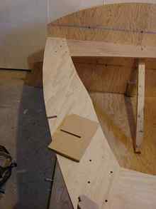
The form is level so the correct slope of the roof can be determined. (About 6” from aft bulkhead to forward bulkhead) Scrap material was screwed in place to give me something to attach the walls too.
The front wall and corner posts were checked and trimmed to suit the width and screwed in place.
A set of side blocks were cut from MDF and slotted to fit flush with the form.
This will keep the side walls from twisting. 3/8” plywood will bend but depending on the manufacturer some is more stiff than others.
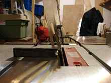
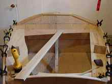
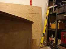
To save myself some pushing and grunt work I bent the two side pieces over a 2x4 and used steamed rags to soak it and let sit overnight.
The roof was given a similar treatment.
With little effort the side pieces were screwed in place front end first.
I clamped a wood batten to the walls to keep a nice even curve as the wood dried/cured.
A level was used to make sure all was plumb.
As that was curing nicely the corner posts were shaped to suit the roof curve with the jig saw and belt sander.
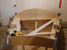
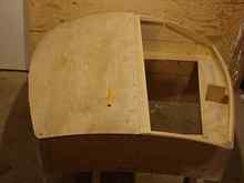
A piece of wood that was originally from my boat building jig was measured and cut to match the curve of the front wall.
It was temporarily screwed in place while I added more scrap wood to the aft wall for mounting the ridge beam and eventually join in the roof plywood.
Slots were cut into the wood on both walls to match my roof ridge beam. This is to provide some support as the roof is put into place. Since the roof is made from 2 pieces of 3/8” plywood this will serve as a joint backing block.
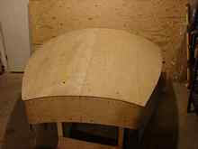
A batten was cut and temporarily screwed to the side walls with about 1/8” protruding up above. This will be planned down to match the curvature of the roof. A roof joist was measured and cut to suit the curvature of the roof near the mid point, just past the future hatch opening. This joist won’t be finished until the whole cabin is installed on the boat.
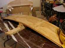
The 2 halves of the cabin roof were temporarily screwed in place with a normal amount of screws on the ridge beam and only a couple of screws on the outer walls. It required only a small amount of hand pressure to hold the plywood down.
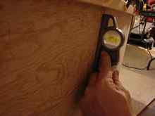
The steam soak worked well and i’m sure there are many ways this can be done to make installation easy. I put my 4ft level along the length of the roof just to check the straightness and it looked fine. Thus far I have only new wood used was 2 sheets of plywood, the rest was leftovers from the build.
Drawings (Click to Download)
Next up, building the hatch cover and slide rails.

|